The general set successfully puts out more peripheral components and requires a larger heat sink. The power amplifier circuit described in this article is simple and easy to manufacture.
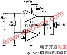
The circuit is shown in Figure 5-107. Connected to a BTL mode with a TDA2822M power amplifier integrated circuit, the external components only have one resistor and two capacitors, no need to install a heat sink, and the playback effect is satisfactory.

Component selection and installation:
The integrated circuit TDA2822M is an 8-pin dual in-line package. If the TDA2822 is not available, the TDA2822 package is identical to the TDA2822M. The difference is that the TDA2822M can operate from 3V to 15V, while the TDA2822 must drop the voltage below 8V. . The numerical value of R1 is not limited, and a carbon film resistor of 10 kΩ is generally used. C1 can be used with 0.1UF and polyester capacitors, and C2 is 100UF/160V electrolytic capacitors.

China TV Antenna,High gain TV Antenna.Factory Price TV Antenna
indoor tv antenna,digital tv antenna,car satellite tv antenna,tv antenna hdtv
Yetnorson Antenna Co., Ltd. , https://www.xhlantenna.com