Abstract: This paper introduces a new type of digital multimeter. The multimeter adds remote monitoring function while retaining the original measurement function. This function sends the measured data of the parent machine to the slave by advanced frequency hopping technology. In order to achieve the purpose of simultaneously displaying the measured values ​​on the LCD screen of the mother machine and the slave machine, thereby satisfying the use of special working environments such as high altitude and small size. The watch uses a low-power PIC microcontroller as a processor to save energy and increase battery life.
Keywords: sub-master digital multimeter; frequency hopping technology; parent machine and child machine; special operating environment; low power consumption
This article refers to the address: http://
O Introduction Digital multimeter is the basic tool for electronic testing. It is widely used in scientific research, factories, schools, measurement and test, etc. due to its high accuracy, wide measuring range, fast measuring speed, small size, strong anti-interference ability and convenient use. Technical field. However, the use of ordinary digital multimeters in special operating environments such as high altitude and small size is subject to certain restrictions. The main performance is that the placement of the multimeter may not be convenient for reading. In response to the above deficiencies, a seed mother digital multimeter is designed, which consists of a parent part for data measurement and a slave part for synchronous display. The wireless frequency hopping communication is adopted between the mother machine and the child machine. The child machine is small, can be worn on the wrist or placed in other convenient observation places, and the mother machine can be placed at random, so that the operator can read the measured data conveniently.
1 System structure and working principle The sub-master digital multimeter is divided into two parts: the parent machine and the slave. The main function of the master machine is to measure the data and send the measurement data to the slave. The slave receives and displays the data.
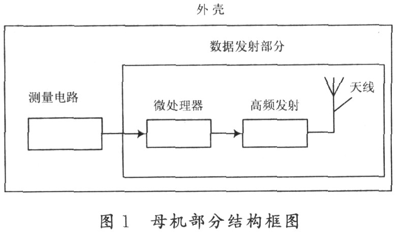
1.1 Mother machine part The mother machine can be divided into four parts: measuring circuit, microprocessor, high-frequency transmitting circuit and antenna. The block diagram is shown in Figure 1.

When the parent machine is set to the sub-mother mode, the measuring circuit transmits the measured data to the microprocessor through the serial port, and the microprocessor drives the high-frequency transmitting circuit to transmit the data by the antenna in the form of frequency hopping communication. The transmitted frequency bands can be distributed in five frequency bands of 315 MHz, 433 MHz, 868 MHz, 915 MHz and 2.4 GHz, each with at least 64 channels, sufficient for frequency hopping communication needs. The microprocessor uses a low-power chip to ensure that the entire system is operating in a low-power state, extending battery life. The high frequency transmitting circuit realizes flexible frequency hopping transmission under the control of micro processing. The transmit frequency, transmit power, receive address, and packet size can be adjusted at will.
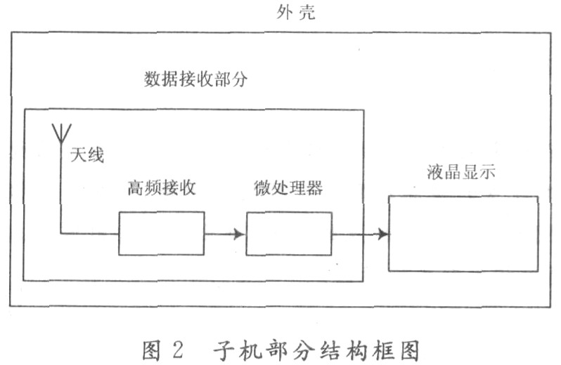
1.2 Sub-machine part Corresponding to the mother machine, the sub-machine can be composed of four parts: antenna, high-frequency receiving circuit, microprocessor and liquid crystal display. The block diagram of the structure is shown in Figure 2.

The sub-machine mainly completes receiving and displaying the data transmitted to it by the parent machine. The frequency point and address must be the same when receiving, and the frequency hopping can be performed according to a certain law under the take-off command of the parent machine. The slave receiving antenna transmits the received high frequency signal to the high frequency receiving circuit for demodulation, and sends the obtained data to the receiving microprocessor for analysis to obtain useful information, and then drives the liquid crystal display to display the data displayed by the parent machine. The currently displayed data for easy reading of measured data.
The corresponding mode between the parent machine and the slave machine can be set by the sending microprocessor of the parent machine and the receiving microprocessor of the slave machine, and the working frequency band and address of the parent machine and the slave machine are set by setting the adapter, when the frequency band and the address of the parent machine and the slave machine are the same. The slave can receive the data transmitted by the parent machine, and the master and the slave hop in the channel distributed in the same frequency band, thereby realizing that multiple daughter-type digital multimeters work independently when they are close to each other, which realizes One-to-one correspondence mode. If the frequency band and address of multiple slaves are set to the same as the frequency band and address of a parent machine, multiple slaves can share the data transmitted by one master to achieve one-to-many mode. Both modes of operation are widely used in normal measurements.
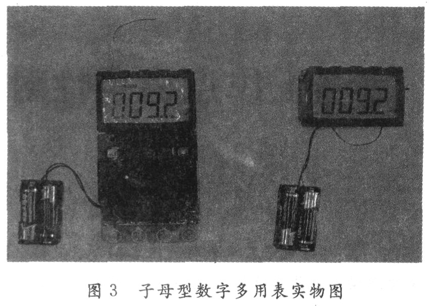
2 Promotion and implementation scheme This design retains the measurement functions of voltage, current and resistance of the ordinary digital multimeter, and adds wireless remote monitoring function, which can meet the needs of ordinary users and can also be used under special working conditions. The multi-meter can be designed as the gear position selection, or can be designed as button gear selection, touch screen gear selection and other styles. The range can be adjusted automatically and manually by button. Figure 3 is the rotary table gear selection digital multimeter. Figure.

3 Conclusion There are many types of digital multimeters, and the measurement range is also very wide. How to better use its advantages is the goal we have been exploring. Through the introduction of the structure and principle of the daughter-type digital multimeter, a function extension of the digital multimeter is demonstrated. It is believed that this extended function will be helpful for engineering measurement.
Crystal Clear Back Sticker,Phone Sticker,Mobile Phone Back Skin,Crystal Clear Phone Skin
Shenzhen Jianjiantong Technology Co., Ltd. , https://www.tpuprotector.com