MulTIsim 10 has a more intuitive and intuitive human-computer interface compared to Protel. The two-stage amplifying circuit of resistance-capacitance coupling is a relatively classic circuit in the analog circuit. The article uses the experimental method to analyze the static working point and dynamic parameters of the two-stage amplifying circuit of the RC-capacitor with the MulTIsim 10 simulation platform. The data and simulation of the actual welding measurement are carried out. Comparing the results, the characteristics of the largest undistorted waveform of the circuit are explored, which has far-reaching practical significance when actually designing the circuit.
In recent years, the development of electronic technology has been changing with each passing day. With the rapid development of computer technology, EDA technology has promoted the design and application of electronic circuits. Based on the simulation platform of MulTIsim 10, the static working point and dynamic parameters of the two-stage amplifying circuit of RC-capacitor are analyzed by the experimental method. The actual welding measurement data is compared with the simulation results, and the characteristics of the largest undistorted waveform of the circuit are explored. The actual design of the circuit has far-reaching practical significance.
1 MulTIsim simulation software and features
Multisim software is an electronic design automation software for circuit simulation and design launched by Canadian image interaction technology company IIT. Its predecessor is the electronic work platform EWB. Since the EWB6.0 version, the company has made large-scale changes to the software. After the upgrade, the software function is more powerful. After being acquired by NI, the company changed its name to NI Multisim, and V10.0 is Its new version of Multisim (ie NI). Compared with other EDA software such as Protel, it has a more visual and intuitive human-computer interaction interface, especially the instrumentation in the instrumentation library is completely different from the actual instrumentation in the real experiment, but it is for the analog-digital circuit. The hybrid simulation function is not inferior, and the results of real circuits can be simulated almost 100%.
2 Multisim simulation RC-coupled two-stage amplifier circuit
2.1 theoretical analysis
The voltage amplification factor of a single-stage amplifying circuit can only reach tens to hundreds of times. To amplify the input weak signal to a level that can push the load, it is often amplified multiple times by multiple single-stage amplifying circuits. Therefore, the practical amplifying circuit is usually composed of two or more stages of single-stage basic amplifying circuits.
Resistor-capacitance coupling is to connect the pre-stage and the post-stage through capacitors, so the DC circuits at each level are not connected to each other, and the static working points of each stage are independent of each other and do not affect each other. This brings great convenience to analysis, design and debugging. Moreover, as long as the coupling capacitor is selected to be large enough, the output signal of the previous stage can be applied to the input of the subsequent stage with little attenuation in a certain frequency range, so that the signal is fully utilized.
2.2 Practice and simulation analysis
As shown in Figure 1, the resistance-capacitance coupling two-stage amplifying circuit is used to solder the physical map, and the signal generator is used to input a 1 kHz, 5 mV sinusoidal signal, and the static operation of the two-stage amplifying circuit is tested with a multimeter under the condition that the oscilloscope observes the distortionless amplification. Observe the maximum undistorted amplified waveform with an oscilloscope and measure the voltage amplification of the two-stage amplification using a transistor millivoltmeter.
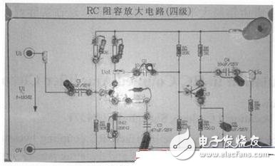
Figure 1 printed circuit board soldering diagram
The components are built according to the circuit diagram, and the virtual signal generator and oscilloscope are connected to the appropriate gear position. Figure 2 shows a circuit diagram of a two-stage amplification simulation of RC coupling.
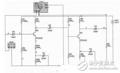
Figure 2 RC series two-stage amplification simulation circuit diagram
Start DC Operating Point Analysis, add the nodes to be analyzed, click Simulate, and the analysis results are shown in Figure 3. From the voltage values ​​at each point, it can be judged that the transistor operates in the amplification region.
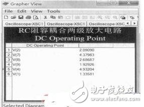
Figure 3 DC working point simulation diagram
The purpose of measuring the static working point is to check the working state of the transistor. From the simulation measurement value, although the theoretical value and the measured value have certain errors, it can be correctly analyzed that the amplifying circuit is in normal amplification work. status.

For best magnification, the static operating point should be adjusted to the midpoint of the AC load line. For this reason, under the normal working condition of the amplifier, gradually increase the amplitude of the input signal, observe the output voltage with an oscilloscope, and when the output waveform has both bottoming and shrinking, the static working point has been adjusted to the midpoint of the AC load line. . Then repeatedly adjust the input signal to maximize the output amplitude of the waveform, and no significant distortion, then use the AC millivoltmeter to measure the U0 effective value.
Gradually increase the input voltage of the signal generator, observe the oscilloscope to maximize the output distortion of the first and second stage output waveforms. This is the difficulty of this experiment. It is necessary to skillfully use instruments such as signal generators and oscilloscopes, and for the most common Three types of distortion: saturation distortion, cut-off distortion, and clipping distortion have a clear understanding. After practice, when the input voltage is 10mV, the waveform reaches the maximum undistorted condition. After observing the waveform, students can find that the multi-level circuit can make the input signal of the circuit get larger amplification, but the disadvantage is that as the number of stages increases, the output waveform is easy to produce distortion, and it needs repeated debugging experience. Figure 4 and Figure 5 show the waveform waveforms of the first stage and two stages after the actual oscilloscope.
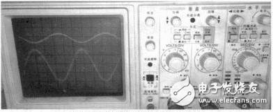
Figure 4 The first stage amplified waveform measured by the oscilloscope
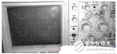
Figure 5 Second-stage amplified waveform measured by the oscilloscope
USB Slip Rings are an increasingly popular way to provide power and data to rotating devices. By using a slip ring, you can avoid having to run cables through a hole in the device's enclosure, which can be difficult and messy. USB slip rings also provide a convenient way to update firmware or change settings on the device without having to open the enclosure. It is commonly used in applications where there is a need to send or receive data or power between a stationary object and a rotating object, such as in an industrial setting where a machine needs to be powered while it is still in use.
Oubaibo's USB Slip Ring, Rotary Swivel Joint manufacturer, chooses the high-quality Senring slip rings, and fiber Rotary Joint products. The company has been in business for many years and is a leading supplier of quality slip ring products. They offer a wide range of products, including high-quality sending slip rings, fiber rotary joints, and more. Their products are affordable and of the highest quality. They are a great supplier for those looking for quality slip ring products.
Usb Slip Ring,Rotary Swivel Joint,Senring Slip Rings,Fiber Rotary Joint
Dongguan Oubaibo Technology Co., Ltd. , https://www.sliprobs.com