The current integrated circuit manufacturing technology is developing rapidly, and SoC (system-on-chip) design has become the development direction of integrated circuit design. As the complexity of SoC design increases, verification work becomes more important and arduous during the development of SoC, which accounts for 40% or 70% of the total cost. The verification process of SoC design not only affects the successful design of the chip, but also And it affects the time to market of the chip, so the correctness of the verification and the reduction of time-consuming has become the key to SoC design.
In traditional design, system-level design uses high-level language C/C++ and other algorithms to describe functional modules, and hardware description language (VHDL or Verilog HDL) is used for verification. Before system verification, the original C/C++ code must be manually converted into VHDL/Verilog HDL code. This conversion process is time-consuming and prone to errors. In the process of system verification, it takes a lot of time to verify the complex module using traditional hardware description language.
In order to improve the efficiency of system-level verification, this article proposes a SystemC-based verification method and process for the motion estimation and compensation unit module (MECU) in the video chip. This method greatly shortens the construction time of the system verification and the time of the system verification process. This article uses SystemC to support designers to model at different abstract levels, and adds a low abstract level interface to the MECU so that the unit can communicate with other models inside the video chip to complete the system-level verification of the entire chip. The simulation results at the end of this paper prove the effectiveness of the design process.
2 SystemC languageSystemC is derived from C++, essentially adding hardware extension libraries and simulation cores to C++, which enables SystemC to model complex electronic systems at different levels of abstraction. It can not only describe purely functional models and system architectures, but also describe the specific implementation of software and hardware, and perform collaborative verification of software and hardware.
SystemC includes the following modeling elements:*Module (module) is equivalent to the C++ class definition and is an entity that can be multi-level. A module can nest other modules and some processes, which is the most basic unit in SystemC.
* Process (process) is used to describe the function of the module and is included in the module. Processes are triggered by events. This triggering method allows processes to be executed in parallel, realizing the parallel characteristics of hardware systems. SystemC includes three different processes.
* Interface (interface) defines a set of methods to achieve goals, but does not implement these methods.
*Channel implements the method of interface definition, which is divided into basic channel and hierarchical channel.
*Port (port) is always associated with a certain interface type. The port can only be connected to the channel that implements this type of interface. The interface method defined in the channel can be accessed through the port module and process.
* Signal (signal) is used to achieve communication between various processes. SystemC provides a variety of signal formats to meet the simulation of different abstract levels from the Register Transmit Level (RTL) to the functional level.
*Event (event) is used to trigger the start and pause of each process, usually multiple events form a sensitive list (sensiTIve list) to jointly determine the state of the process.
*Clock The clock plays a very important role in the design of synchronous circuits. In essence, it is a special signal that provides a time reference for the simulation process.
The above modeling elements enable SystemC to build a hardware platform smoothly.
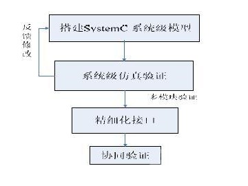
3 Modeling method based on SystemCIn the system-level verification process, for complex algorithm models only need to establish reference models (Reference Models), build a verification platform, and observe some important functions of the model (algorithms, processes, etc.), without knowing the details of the RTL level. It is easy to build a reference model using the transaction-level modeling method (TLM, TransacTIon Level Modeling) technology. A complete chip is composed of multiple functional modules. Using SystemC to build models of complex algorithm units can shorten the functional verification time, while the verification of some simple models needs to be at the RTL level. In order to realize the communication between modules of different abstract levels, this article refines the interface of the complex unit model established by SystemC. This paper proposes the SystemC modeling verification process for the actual chip unit.

(1) Build SystemC system-level model:
Using SystemC based on C++ can easily build a system-level model. Use SystemC to describe the system function to be realized, mainly describe the algorithm, structure, etc. of the system, without considering the change of register value in each clock cycle. Only by using SystemC modeling for complex algorithm units can SystemC take advantage of the time savings in modeling and verification.
(2) System-level functional simulation:
Use the tools that support SystemC to simulate and verify the system function of the established model, observe the results and continuously feedback and modify until the simulation is correct.
(3) Refined interface:
The refined interface is the key to the multi-module verification process. Because in the system-level verification of a single complex unit, the abstraction level is very high, only its functionality needs to be considered. When multiple modules are verified, the external unit model may be built at the RTL level. In this case, it is necessary to take advantage of SystemC's ability to model at different abstract levels to implement different abstraction layer modeling in a larger module, that is, to interface with the external model The abstraction level is reduced to the RTL level. The process of refining the interface requires adjusting the input and output data bit width according to the external module interface, setting the sensitive event list, and controlling the data transmission strictly according to the external clock to ensure smooth communication with the external module.
(4) Collaborative verification:
Verify the correctness of multiple modules working together. If errors are found at this time, the design can be modified in time to improve chip design efficiency. The module with the correct verification result can be used for the back-end process, and the established verification platform can also be used as an externally driven test platform for software verification.
4 Application examples4.1 Principle of MECU
The coding and decoding process of video codec chips widely used in mobile phones includes DCT transformation, quantization, VLC encoding, inverse DCT transformation, inverse quantization, motion estimation, motion compensation, interpolation calculation, edge filling and other steps. Among them, the motion estimation and compensation part It is an important link to realize the time redundancy of compressed images. Due to the complexity of the algorithm, this part occupies most of the coding and decoding time. The verification of the MECU module is the most workload link in the entire chip verification.
In this article, the MECU uses the MVFast (MoTIon Vector Field AdapTIve Fast Motion Estimation) algorithm to implement ME/MC: the ME part implements motion prediction during the image encoding process, calculates the motion vector, and completes the macroblock encoding type (MBmode) judgment and motion vector encoding at the same time Type judgment; in the image encoding process, the MC part completes the YUV interpolation process according to the motion vector of each block input to output the motion reference block data and the current processed block data; in the image decoding process, completes the interpolation process and outputs the reference block data.
4.2 Module construction
When the Verilog language is used to directly establish the MECU model for chip design, the modeling process is time-consuming due to the complex MECU algorithm. During Verilog modeling, the system verification engineer needs to wait for the model to be established, which increases the chip design cycle. On the other hand, it takes a long time to verify the MECU model established by Verilog. Since the modeling time based on SystemC is 3 to 4 times shorter than that of Verilog modeling, and the verification process has the advantage of rapidity, this article tries to use SystemC for the preliminary modeling and verification work.
According to the verification method introduced in the second part of this article, first establish the MECU hardware simulation model for functional verification, and then verify the peripheral module design based on the correct hardware model to achieve system-level verification of the entire chip.
The first step is to use SystemC to perform system-level modeling of ME and MC respectively. When the two modules of ME and MC are established, only the respective algorithm functions of ME and MC and the communication between the two modules need to be realized, so precise timing modeling is not required. Based on the realization of MVFAST algorithm model in C language, ME and MC are respectively programmed into simulatable modules MEU and MCU with SC_MODULE, and the internal functions are realized by Process. After the model is established, build a platform for functional verification and observe whether the data changes after ME and MC fully meet the algorithm requirements.
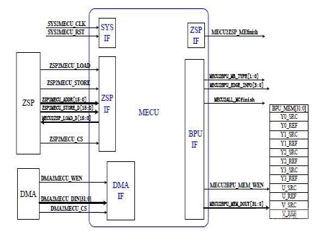
After the functional verification of the MEU and MCU models is completed, it needs to be verified with other modules in the chip. Because the peripheral modules of the MECU are modeled at the RTL level and the data is processed strictly according to the clock, the MECU interface must be refined. This experiment adds SYS_IF, ZSP-IF, DMA-IF and BPU-IF modules to communicate with peripheral modules. These interface modules include input and output ports that match the peripheral modules, and the clock strictly controls the data transmission.

4.3 Interface module description
(1) SYS_IF provides MECU's external clock and reset signal interface. These two control signals are valid for all modules in MECU.
(2) The triggering of MEU and MCU is controlled by the start signal generated by external ZSP, and the control register contained in MECU is also controlled by ZSP. The addition of the ZSP_IF module enables ZSP to read and write MECUs.
(3) The data that needs to be processed in the encoding and decoding process of the MECU model is provided by the ZSP control DMA, so the DMA_IF module is added to realize the communication with the DMA and carry the data for MECU processing.
(4) Finally, the data generated by the MC is transmitted to the BPU through the BPU_IF module (for comparison of software and hardware results).
As can be seen from the above structure, MECU includes six modules: ME, MC, SYS_IF, ZSP_IF, DMA_IF and BPU_IF. ME and MC as the core function modules implement the algorithm of the MECU unit. The four interface modules SYS_IF, ZSP_IF, DMA_IF and BPU_IF strictly control the data transmission by the clock to realize the communication function with the peripheral modules.
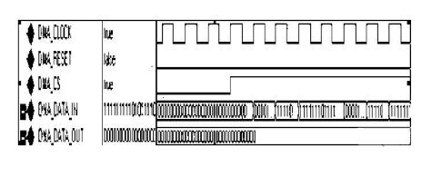
5 Analysis of simulation results Use the aforementioned SystemC model for simulation verification, using a group of 352*288 pixel images as the simulation object, and using Mentor's Modelsim as the simulation tool. First establish a test platform, simulate the external ZSP and DMA to provide control signals and process data, and then use Modelsim to perform simulation verification and timing analysis.

The data results obtained by the simulation fully conform to the expected value of the algorithm, which proves the correctness of the built model. Time sequence analysis results show that: using SystemC to encode a macro block (16*16 pixels) of an image requires an average of 680 clock cycles, of which the ME and MC parts occupy 11 clock cycles; the traditional hardware description language Verilog modeling is used to verify one The coding of the module requires 3000 clock cycles on average, of which ME and MC occupy 2200 clock cycles. Comparing the verification time of ME and MC based on the two modeling methods of SystemC and Verilog, it is found that the pure functional verification time using SystemC is about 200 times shorter than the verification time using Verilog, so the advantage in verification time is significant.
6 SummaryThis paper has conducted an in-depth study on the SystemC verification method. For the verification of the MECU unit of the video codec chip, a modeling process using SystemC verification is proposed. The port refinement method enables the chip to be modeled and verified at different abstract levels. Currently, it is not used much in domestic verification. The simulation result proves the effectiveness of the process, and the time is significantly shortened compared with the traditional hardware description language verification.
For the passed long time, the main sizes of laptops fell into three ones, 13 Inch Budget Laptop For Student, especially elementary or middle school or prefer smaller size; 17.1 inch graphic laptop for the ones prefer higher performance and bigger screen; 15.6 inch Budget Working Laptop for all others left. However, 14 Inch Laptop is becoming the main trend now, 11 Inch Laptop and 10.1 Inch Laptop also available at the market and our store.
14 Inch Gaming Laptop with i3, i5, i7 10th generation is a great choice for those who do heavy jobs and often go to business trip, like interior designers, engineering or architecture students or workers, etc. Of course, 14 Inch Laptop With Graphics Card, 16.1 inch i7 16gb ram 4gb graphics laptop also alternatives.
Of course, other Laptop 14 Inch I5 or 14 Inch To CM Laptop you can see also at this store. To save time, you can contact directly and share exact configuration so that we can provide right and valuable information quickly for you.
Except business, any we can do in China, just let us know also.
Not only want to cooperate, but also hope be your friend in China.
14 Inch Laptop,14 Inch Gaming Laptop,Laptop 14 Inch I5,14 Inch Laptop With Graphics Card,14 Inch To Cm Laptop
Henan Shuyi Electronics Co., Ltd. , https://www.sycustomelectronics.com