To answer the question of the title, we must first understand a few principles.
1. Definition of single-phase earth fault
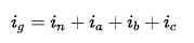
We set the three-phase currents as ia, ib, and ic, respectively, and have the following relationship:

If the three-phase current is balanced, that is, Ia=Ib=Ic, it can be written as:

We can easily use the knowledge of the trigonometric function in middle school to prove that the sum of the three sinusoids in the brackets is equal to zero.
The right side of the equal sign is actually a three-phase unbalanced current. We can see that the neutral current In is the same as the three-phase unbalanced current. Therefore, when the three phases are balanced, the current on the bus of the neutral line N is zero.
As a reminder, although the current on the neutral N bus is zero when the three phases are balanced, the current on the neutral branch is not equal to zero. In fact, the current on the neutral branch is equal to the phase current of a phase and is in the opposite direction.
Now, we combine the neutral current and the three-phase current together to calculate the phasor sum as follows:
What will happen?
We have found that even if there is a three-phase imbalance, the value of ig is still zero. which is:

Let's look at Figure 1 in the figure below. The load is actually the same three resistors installed on the three phase lines. It is obvious that the three phases are balanced. On the other hand, the phase A in Figure 2 has one more resistor, so the three phases are not balanced. However, whether in Figure 1 or Figure 2, the phasor sum of the neutral current and the three-phase current is always equal to zero.
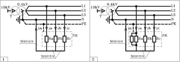
Note 1: The current on the N line bus in Figure 1 is equal to zero, but the N line branch current is not equal to zero.
Note 2: The grounding system of Figures 1 and 2 is TN-S.
Now we assume that there is a leakage ias in phase A. Let's see what happens:
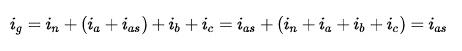
We call ig the residual current, and its value reflects the value of the leakage current.
We look at the picture below:
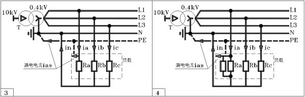
In both Figure 3 and Figure 4, phase A has a leakage current to the load case, and the leakage current ias returns to the power supply along the PE line. From the previous explanation, we already know that the residual current can reflect the leakage current.
In low-voltage distribution systems, ig is also called single-phase ground fault current.
2. Single-phase ground fault current acquisition method
We look at the picture below:

In Figure 5, we installed a zero-sequence current transformer core upstream of the load, and let three phase lines and one N line pass through the core at the same time. As a result, we can measure the leakage current ias in the secondary winding of the zero-sequence current transformer.
In addition, in Figure 5 we can also install a zero-sequence current transformer on the ground PE to directly measure the leakage current.
The two methods in Figure 5 are very common. The problem is that the internal space of the circuit breaker is small. When the three-phase current is very large, it is impossible to install the zero-sequence current transformer inside the circuit breaker. In this case, other ways must be taken.
We look at Figure 6:
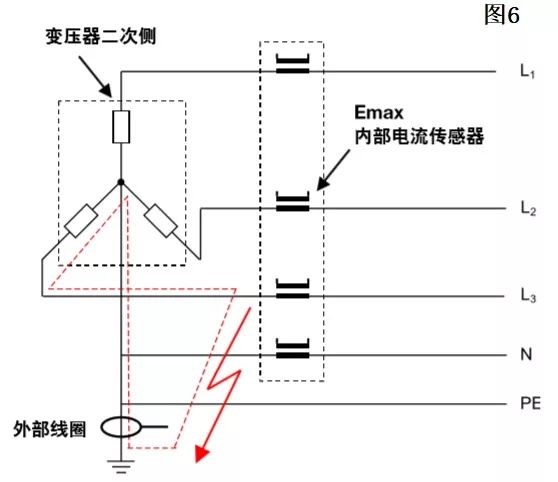
FIG. 6 is a method of acquiring residual current inside the frame breaker Emax of ABB.
In Figure 6, we see that four current sensors with Rogowski coils are installed inside the circuit breaker. They collect three-phase current and N-line current, respectively, and then sum up the phasors of the four currents inside the trip unit. This solves the residual current.
The second method in Fig. 6 is to directly measure the residual current from the ground-mounted zero-sequence current transformer and then input it to the circuit breaker trip unit.
The first method is called the G protection measurement of the circuit breaker and the second method is called the external G protection measurement.
Now we can answer the question of the title. Let's look at what the title question is:
1) What is the difference between ground protection, leakage protection and neutral protection of ACB frame circuit breakers?
2) Two kinds of ground fault protection: 1. Residual current type; 2. Ground current return type. What's the difference between the two?
First answer the second question:
From the previous description we already know that there are two types of G protection for ACB frame circuit breakers:
The first is for single-phase ground faults that occur downstream of the circuit breaker, including single-phase ground faults that occur at the circuit breaker outlet, and single-phase ground faults that occur at the feeder cable. This single-phase ground fault can be measured by the phasor sum of the three-phase current and the N-line current.
The first type of single-phase ground fault is the so-called residual current type.
The second type is for a single-phase ground fault that occurs upstream of the circuit breaker. This single-phase ground fault can be measured by the zero-sequence current transformer of the transformer ground.
The second single-phase ground fault is the so-called earth current return type.
Need to remind is:
The residual current protection has three current ranges: the first residual current range is 16mA to 30mA, which is dedicated to personal safety protection; the second residual current range is 30mA to 100mA, which also serves as personal safety protection and electrical fire protection; The residual current range is greater than 100mA and is dedicated to electrical fire protection.
Since the case current of the frame ACB breaker is generally not less than 630A, and the maximum is 6300A, the G protection of the frame ACB breaker is generally used for electrical fire protection.
Then answer the first question:
ACB's single-phase ground fault protection and leakage protection are one and the same thing.
As for the neutral line protection, it mainly refers to the three-phase unbalanced current protection and the neutral current protection of the third harmonic.
We already know that the neutral current is the phasor sum of three-phase currents. However, for the third harmonic, the neutral current is not a phasor sum but an algebraic sum, so the neutral current of the third harmonic is particularly large. Therefore, if there is a third harmonic in the power grid, the cross section of the neutral bus must be equal to the cross section of the phase bus.
In addition, if the ACB has neutral protection, the ACB must be a four-pole circuit breaker.
Let's look at the Emax protection circuit breakers for ABB with neutral protection as follows:

We see that the protection of the N pole is consistent with the protection of the pole where the phase is located.
==============
Give a supplement:
Do not equate phasors with vectors (vectors).
The two vectors are multiplied and then multiplied by the sine of the angle between them, called the multiplication of vectors. The result of the vector cross-multiplication is still a vector, such as cross-product of arm and force, and the result is moment. Moment is a vector.
The cross-section of the voltage phasor and the current phasor is the result of the reactive power and the reactive power is the scalar.
So phasors and vectors cannot draw equal signs.
Flat Control Cable Also known as festoon cable, this flat cable fits in confined spaces such as overhead cranes and hoists. It sends signal and data to operate, measure, or regulate automated equipment.
Raw cable can be UL2651, UL20251 ,etc
Flat cable, IDC cable, flat cable wiring, ribbon cable harness, flexible flat cable
ETOP WIREHARNESS LIMITED , https://www.oemwireharness.com