Introduction Under the premise that the current level of automotive electronics has become an important international standard for measuring the advanced level of automobiles, all countries are developing this industry, constantly applying high and new technologies, and improving the performance of automotive electrification, in order to obtain a larger market. It is in this environment that stimulated and promoted the continuous development of the automotive electronics industry.
As we all know, poor stability and short life are common problems of current car voltage regulators. The instability of the regulator will cause the output voltage of the generator to be unstable, so that the power supply voltage of the vehicle's electrical equipment will fluctuate greatly. The normal operation of the vehicle circuit is unfavorable, and it also reduces the life of the electricity. The short life of the regulator will not only bring economic burden, but also disadvantageous to the stability of the generator output voltage.
The voltage regulator is designed as a monolithic CMOS integrated circuit, thereby reducing the volume of the regulator, so that it can be made with an alternator. This not only improves the stability of the regulator, improves the power supply quality of the vehicle, effectively extends the service life of automotive electronic equipment, but also adapts to the current development trend of small size and large output power of automotive alternators. At the same time, the design also adapts to the current pursuit of the regulator "high performance, multi-function, high power, long life".
1 Circuit principle and structure The principle block diagram of the automobile electronic regulator is shown as in Fig. 1.

When the car starts to join the input voltage, the reference voltage source generates the reference voltage for internal circuit use; the error amplifier receives the output voltage signal; the overcurrent protection circuit samples the output current of the power tube; the thermal protection circuit checks the temperature of the circuit; The flow safety zone protection and overheating protection circuit are fed into the power tube together. When there is an abnormal phenomenon, the adjusting tube will be turned off to adjust the voltage and protect.
2 Circuit design
2.1 Front-end reference source The front-end reference voltage source in the designed chip circuit is to provide a stable reference voltage for the power supply voltage and temperature to the subsequent differential comparison circuit, which is then sampled by the differential comparison circuit. The voltage output from the generator is compared to control the output of the generator. The circuit is shown in Figure 2. In Figure 2, M1, M2, and M5 form a mirror current source, making the currents flowing through the three tubes equal, all of which are I; M3, M4 form a voltage clamping circuit to keep the voltages at A and B consistent. The mirror current source and the voltage clamping circuit together form a PTAT source, and use its positive temperature coefficient to compensate for the negative temperature coefficient of the PN junction, thereby obtaining a reference voltage that basically does not change with temperature.

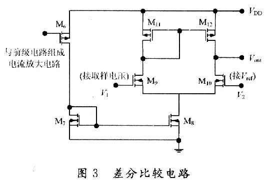
2.2 Differential comparison circuit The function of the differential comparison circuit is to compare the reference voltage from the front-end reference voltage source with the sampling voltage of the generator. When the generator output voltage is lower than 14 V, the excitation current adjustment tube works normally, the excitation current flowing through the generator rotor winding rises rapidly, and the generator output voltage also rises rapidly. When the generator output voltage reaches 14 V, the differential output voltage is sufficient to drive the subsequent control circuit to control the excitation current adjustment tube grid to ground, and the grid current is divided away, which reduces the excitation current of the generator rotor winding, thereby reducing power generation. The output voltage of the machine reaches the voltage regulation function. The circuit is shown in Figure 3.
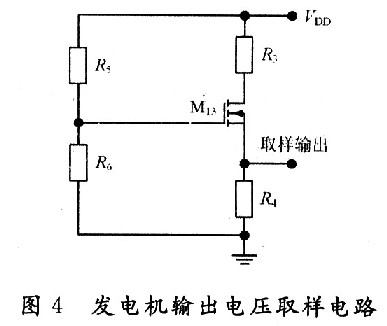
2.3 Sampling circuit of generator output voltage The function of the automobile regulator is to adjust the output voltage of the generator and control it to a certain value. Since you want to control the output voltage of the generator, you need to sample the output of the generator. There are two voltage sampling methods for electronic regulators, namely sampling the output voltage of the generator and sampling the voltage of the battery. The double sampling method is mostly used in the separation device regulator. In this design, the front-end reference voltage source has provided an accurate comparison voltage, so it is sufficient to sample the output voltage of the alternator. The sampling circuit is shown in Figure 4. Resistors R5, R6 and M13 in Figure 4 form an energy-saving circuit. When the car stops working, this part of the circuit cuts off the connection between the regulator circuit and the battery to avoid the loss of battery power.
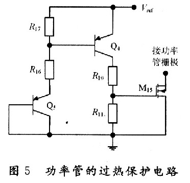
2.4 Temperature protection circuit The power device handles high voltage and large current. High voltage and large current will cause the temperature of the device to rise. When the temperature is high to a certain degree, the device will be damaged due to overheating. It is necessary to design an overheat protection circuit to protect it from temperature. The temperature protection circuit of the power tube is shown in Figure 5. Because the temperature characteristic of MOS device is better, its parameter (mainly threshold voltage) changes with temperature very little, so this part of the circuit is realized by PNP tube. In the circuit, the B and C poles of Q5 tube are connected to form a PN junction, and the temperature of the power tube is detected. When the temperature of the power tube reaches the limit temperature (here 150 ℃), the NMOS tube M15 is controlled by the PN junction voltage. This tube is also used as a switch tube) to conduct, diverting the input current of the power tube grid, reducing the current flowing through the power tube, thereby reducing the temperature of the power tube, and achieving the overheat protection of the power tube.
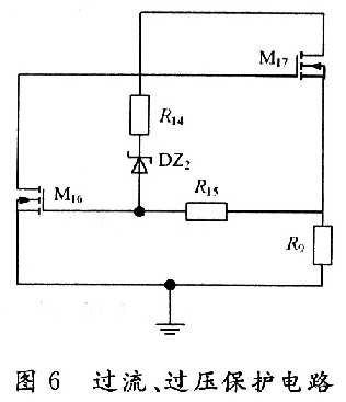
2.5 Overcurrent and overvoltage protection The overcurrent and overvoltage protection circuit of the power tube in the regulator is shown in Figure 6. In Fig. 6, the M17 tube is the excitation current adjustment tube (that is, the high-power tube). The resistors R9 and M16 form an overcurrent protection circuit. The resistor R14 regulator tube DZ2 and M16 tube form an overvoltage protection circuit for the power tube, among which M16 and M14 The tube is also used as a switch tube.
 3 Overall circuit and simulation
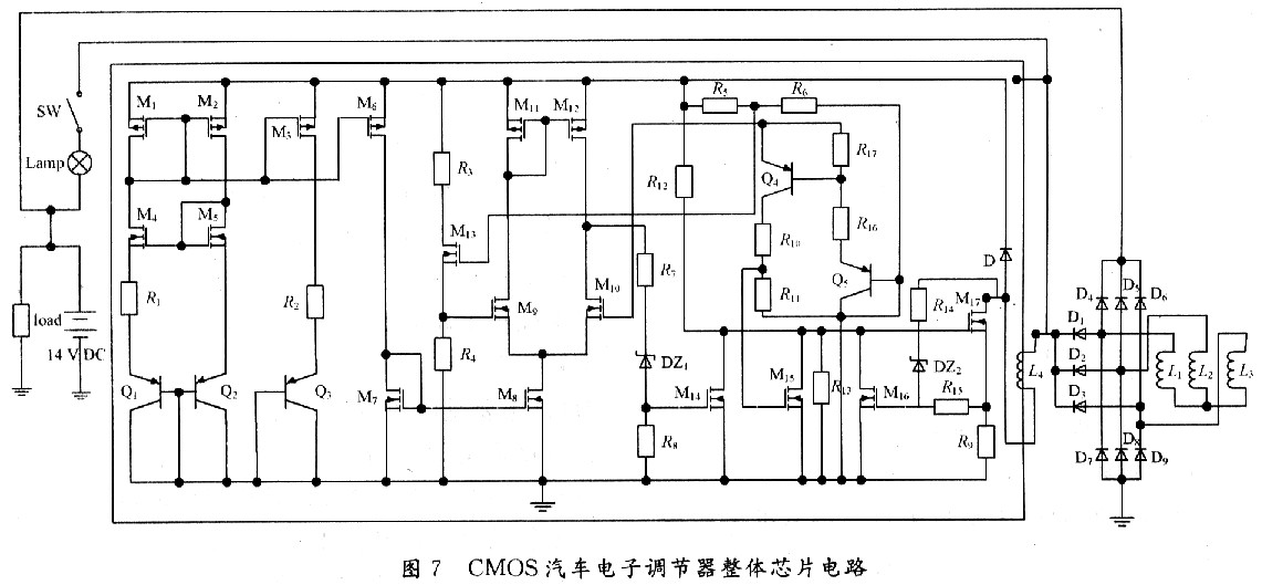
3.1 Circuit integration According to the above design of each part of the regulator chip, combining them together is the overall circuit of the regulator to be designed, as shown in Figure 7.
3.2 Functional verification The simulation verification waveform is shown in Figure 8, where the abscissa is the generator output voltage and the ordinate is the change in the base voltage of the excitation regulator. Figure 8 (a) is the verification waveform at a fixed temperature, and Figure 8 (b) is the verification waveform at full temperature.
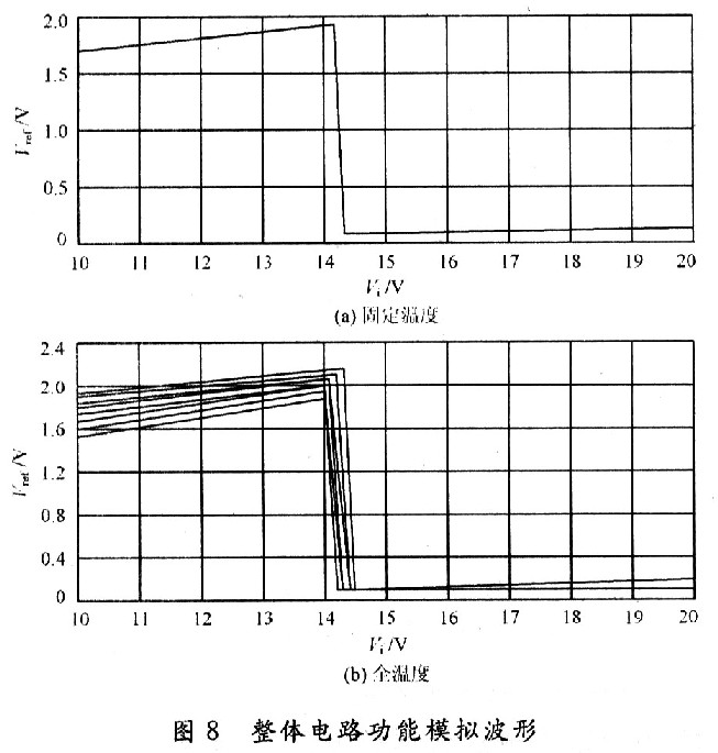
It can be seen from Fig. 8 that when the voltage at the output end of the generator has not reached the regulation voltage, the base potential of the regulator is close to zero potential, and the regulating tube is cut off at this time. It can be obtained from Fig. 8 (b) that the regulator can still obtain good regulation performance under different working temperatures.
4 Conclusion This paper proposes a monolithic CMOS automotive electronic regulator. This chip mainly adjusts the current in the excitation coil of the generator by controlling the conduction and cut-off of the regulator tube, and then stabilizes the output voltage. The automotive power generation system composed of the chip has the characteristics of high reliability, small number of peripheral components, low cost, and convenient use. It is of great significance for breaking the monopoly of foreign automotive electronic core technology.
LED Spot light we used is Sanan chip, and the driver we used is our brand. It is made by plastic frame and aluminum back cover. We are the manufacturer of producing energy saving interior lighting. There are three adjustable color temperatures with cool white, warm white and natural white of down lights. What's more, it is adjustable among the three colors Red/Blue/Green/Pink. The unique feature of led Slim Panel Light is: CRI>80, PF>0.5. These panels are mainly apply to store, plaza, mall, supermarket, counter, display window, show room Counter, museum lighting.
Commercial Electric LED Downlight,Aluminum LED COB Downlight,Super Bright Ajustable Downlight Polished
Jiangmen Lika Lighting Electrical Appliances Co., Ltd , https://www.lika-led.com