Radio frequency identification (radio frequency idenlificaTInn, RFID) is an automatic identification technology that emerged in the 1990s. RFID technology has many advantages that barcode technology does not have. It can be applied to second-generation citizen ID cards, city card, financial transactions, supply chain management, electricity publication fee (ETC), access control, airport. Baggage management, public transportation, container identification, livestock management, etc., therefore, it is very important to master the technology of manufacturing RFID chips. At present, the increasing demand for applications puts higher demands on RFID chips, requiring them to have larger capacity, lower cost, smaller size and higher data rate. According to this situation, this paper proposes a long-distance, low-power passive UHF UHF RFID transponder chip RF circuit.
The commonly used operating frequencies of RFID include low frequency 125 kHz, 134.2 kHz, high frequency 13.56 MHz, ultra high frequency 860 to 930 MHz, microwave 2.45 GHz, 5.8 GHz, and the like. Because the low frequency is 125kHz, 134.2kHz, the high frequency 13.56MHz system uses the coil as the antenna, and adopts the method of inductive coincidence. The working distance is relatively close, generally not more than 1.2m, and the bandwidth is limited to several kilohertz in Europe and other regions. However, ultra-high frequency (860 ~ 93Uh1Hz) and microwave (2.45GHz, 5.8GHz) can provide a longer working distance, higher data rate, smaller antenna size, and thus become a hot research field of RFID.
The RF circuit chip proposed in this paper is developed by the Chartered 0.35μm 2P4M CM0S process supporting Schottky diodes and electrically erasable programmable read-only memory (EEPROM). Schottky diodes have lower series resistance and forward voltage, which can provide higher conversion efficiency and lower power consumption when converting the received RF input signal energy to DC power. With an effective isotropic radiated power (EIRP) of 4W (36dBm) and an antenna gain of 0dB, the RF circuit chip operates at 915MHz with a read range greater than 3m and an operating current of less than 8μA.
1 RF circuit structureFigure 1 is a UHF RF1D transponder chip system diagram, which mainly includes a radio frequency circuit, a logic control circuit and an EEPROM. Among them, the RF circuit part can be divided into the following main circuit modules: local oscillator and clock generation circuit, power-on reset circuit, voltage reference source, matching network and backscatter circuit, rectifier, voltage regulator and amplitude modulation ( AM) demodulator, etc. There is no external component except the antenna. The antenna part adopts a dipole structure and is matched with the input impedance of the rectifier through the matching network as the sole energy source of the whole chip. Its equivalent model is shown in Figure 2. The real part of the dipole antenna impedance consists of two parts, Rra and Rloss, where Rra is the radiation impedance of the dipole antenna, which is inherent to the dipole antenna, typically 73Ω, which characterizes the antenna's ability to radiate electromagnetic waves externally; Rloss The ohmic resistance that is used to make the metal used in the antenna generally produces only heat. The imaginary part X of the antenna impedance is generally positive, because the antenna is generally inductive to the outside, and the size of the equivalent inductance generally depends on the topology of the antenna and the material of the substrate. The rectifier converts the RF input signal power coupled to the DC voltage required by the chip. The voltage regulator stabilizes the DC voltage at a certain level and limits the amplitude of the DC voltage to protect the chip from breakdown due to excessive voltage. The AM demodulator is used to extract a corresponding data signal from the received carrier signal. The backscatter circuit changes the impedance of the RF circuit by means of a variable capacitor to transmit the transponder data to the RFID interrogator or card reader. The power-on reset circuit is used to generate a reset signal for the entire chip. Unlike the 13.56 MHz high frequency (HF) transponder, the 915 MHz UHF transponder cannot divide the local clock from the carrier, but can only clock the digital logic portion by building a low-power local oscillator. All of these circuit modules will be explained in detail below.
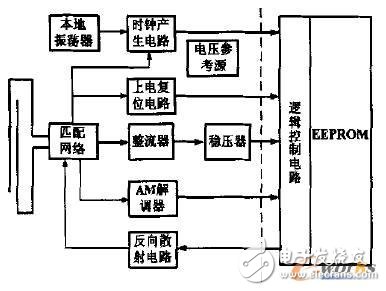
Figure 1 UHF RF1D transponder chip system diagram
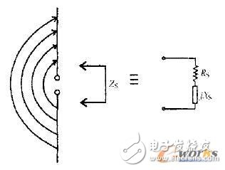
Figure 2 Equivalent electrical model of the transponder antenna 2 Circuit design and analysis
2 circuit design and analysis2.1 Rectifier and Regulator Circuit
In this paper, the Dickson charge pump composed of Schottky diode is used as the rectifier circuit. The circuit schematic is shown in Figure 3. This is because Schottky diodes have lower series resistance and junction capacitance, which can provide higher conversion efficiency and lower power consumption when converting the received RF input signal energy to DC power. All Schottky diodes are connected together by poly-poly capacitors, in which the vertical capacitance is charged and stored in the negative half cycle of the input voltage Vin, and the lateral capacitance is charged and stored in the positive half cycle of Vin, thereby generating DC. High voltage, the voltage it produces is:
VDD=n·(Vp,RF-Vf,D)
Where Vp, RF is the amplitude of the input RF signal, Vf, D is the forward voltage of the Schottky diode, and n is the number of stages of the charge pump used.
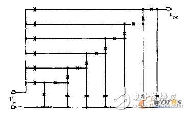
Figure 3 rectifier circuit diagram
Figure 4 is a circuit diagram of a voltage regulator. The circuit is to stabilize the DC voltage output from the rectifier at a certain level and provide a stable working voltage for the entire transponder chip to ensure that the DC voltage amplitude is not changed due to the physical position change of the transponder chip, avoiding possible The resulting chip breakdown, thereby protecting the transponder chip. The circuit adopts a self-biased Cascnde structure. The circuit structure is chosen because the Cascnde structure has the isolation function of the common-gate tube, which makes it have a good ability to suppress power supply fluctuations, thereby improving the power supply rejection ratio (PSRR). Ensure that the current of the two branches is basically stable. Wherein the area ratio of Q1 to Q2 is 1:8. In addition, unlike general HF RFID transponders, we have adopted a low-power voltage reference source with a low-voltage startup circuit to reduce the overall power consumption of the chip.
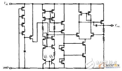
Figure 4 regulator circuit diagram
KNM5 Series Moulded Case Circuit Breaker
KNM5 series Moulded Case Circuit Breaker is MCCB , How to select good Molded Case Circuit Breaker suppliers? Korlen electric is your first choice. All moulded Case Circuit Breakers pass the CE.CB.SEMKO.SIRIM etc. Certificates.
Moulded Case Circuit Breaker /MCCB can be used to distribute electric power and protect power equipment against overload and short-current, and can change the circuit and start motor infrequently. The application of Moulded Case Circuit Breaker /MCCB is industrial.
Korlen electric also provide Miniature Circuit Breaker /MCB. Residual Current Circuit Breaker /RCCB. RCBO. Led light and so on .
KNM5 series Molded Case Circuit Breaker,Small Size Molded Case Circuit Breaker,Electrical Molded Case Circuit Breaker,Automatic Molded Case Circuit Breaker
Wenzhou Korlen Electric Appliances Co., Ltd. , https://www.korlen-electric.com