1 Introduction
This article refers to the address: http://
Since the 1980s, with the continuous development of automotive electronics technology, there are more and more electronic control units on automobiles, such as electronic fuel injection devices, anti-lock braking devices (ABS), airbag devices, and electronically controlled door and window devices. And active suspension and more. In this case, if the traditional point-to-point parallel wiring method is still adopted, the number of wires on the car will increase sharply, the wiring becomes more and more difficult, the wire quality accounts for more and more the quality of the whole vehicle, and the complicated circuit is also reduced. The reliability of the car increases the difficulty of maintenance. In order to meet the rapidly increasing application needs of automotive electronic equipment, the controller area network CAN came into being. At present, in the field of automotive design, CAN has almost become a technical means that must be adopted, especially in Europe, such as BENZ, BMW, etc., using CAN bus to realize the internal control system of the vehicle and each detection and execution. Inter-agency data communication [1]. The car CAN bus data recorder can collect the CAN CAN bus data information in real time. Its development is of great significance for familiarizing and mastering the communication protocol and information content of the car CAN bus, and for the application research of automobile fault repair and automotive network technology.
2, CAN bus introduction
CAN is the abbreviation of Controller Area Network, which was developed by Bosch and several semiconductor manufacturers in Germany. CAN bus is a serial multi-master controller LAN bus. It has high network security, communication reliability and real-time performance, and is simple and practical, and the network cost is low. It is especially suitable for automotive computer control systems and industrial environments with harsh ambient temperatures, strong electromagnetic radiation and high vibration. The CAN bus can effectively support distributed control or real-time control. The communication medium of the bus can be twisted pair, coaxial cable or fiber [2-3]. Its main features are as follows:
• The CAN bus is a multi-master bus, and each node can send information to other nodes on the network at any time, regardless of master-slave;
• The CAN bus uses a unique non-destructive bus arbitration technology, and high-priority nodes preferentially transmit data, so the real-time performance is good;
• CAN bus has the function of transmitting data in point-to-point, point-to-multipoint and global broadcast;
• CAN bus adopts short frame structure, the maximum number of valid bytes per frame is up to 8, the data transmission time is short, and there are CRC and other verification measures, and the data error rate is extremely low;
• When a node on the CAN bus has a serious error, it can automatically leave the bus, and other operations on the bus are not affected;
• When the CAN bus system is expanded, the new node can be directly hung on the bus, so the wiring is small, the system is easy to expand, and the modification is flexible;
• The maximum transmission rate of the CAN bus can reach 1Mb/s, and the direct communication distance can reach up to 10km (the rate is below 5kbps);
• The number of nodes on the CAN bus depends on the bus driver circuit. Up to 110 in standard frames (11-bit message identifiers) and unlimited in extended frames (29-bit message identifiers).
3, CAN bus data recorder hardware design
When the CAN bus data logger is working, it should be connected to the CAN bus of the car to become a CAN node to collect CAN data information. The system hardware structure adopts the circuit structure shown in FIG. The core modules are described below.
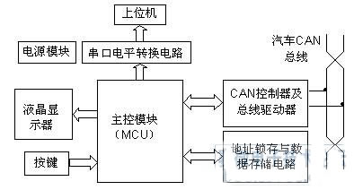
Figure 1 Block diagram of CAN bus data logger
(1) Main control module (MCU)
The main control module of this system adopts AT89C52 of ATMEL company. It is a low-power, high-performance 8-bit CMOS microcontroller with 8KB of flash memory and is fully compatible with industry standard MCS-51 instruction systems and pins. The superiority of the AT89 series is that its on-chip flash memory can be programmed and erased 1000 times, and the data is not easily lost, and the data can be stored for 10 years.
(2) Data storage circuit
The CAN bus data transmission rate is high, and the single-chip microcomputer has a slow operation speed and heavy tasks. To ensure that data is not lost during data acquisition, the microcontroller externally expands the data memory. When the CAN module receives a frame of data on the CAN bus of the car and causes the MCU to interrupt, the interrupt service routine stores the received data to the external data memory and immediately interrupts the return. The cumbersome work of processing and displaying the data is completed in the main program. . In this way, the integrity and real-time performance of CAN bus data reception is ensured.
(3) Human machine interface module
The CAN bus data logger uses OCMJ5×10B Chinese liquid crystal display module to display information and received data. The module contains dot matrix national standard simplified Chinese characters and ASCII code, which can realize text display. Its user hardware interface uses REQ/BUSY handshake protocol, which is simple and reliable. BUSY is active high, indicating that OCMJ is busy and cannot accept commands; when BUSY=0, it indicates that OCMJ is idle [4]. At the same time, when REQ=1, the OCMJ is notified to process the data on the current data line. The system uses the single-chip microcomputer P1.6 and P1.7 as the communication port with the REQ and BUSY of the liquid crystal display module.
This system mainly has settings, increase and decrease buttons. Key input is realized by using single chip microcomputer P1.0-P1.2.
(4) Communication module
The CAN bus data received by the CAN bus data recorder can be displayed in real time on the liquid crystal display, or can be transmitted to the host computer for display or data processing and data analysis by using the serial communication interface. The system uses the level conversion chip MAX232 to realize the serial data communication between the single chip and the PC.
(5) CAN module
The CAN controller used in this system is SJA1000. SJA1000 is a CAN controller manufactured by PHILIPS that supports both CAN 2.0B and CAN 2.0A. The CAN transceiver used with the SJA1000 is the PCA82C250, which is a CAN controller and physical bus interface chip from PHILIPS that provides differential transmission and reception to the bus. It is fully compatible with the ISO 11898 standard and has three different modes of operation: high speed, slope control and standby, which can be selected according to the actual situation. The basic method of CAN module bus controller and bus driver connection is shown in Figure 2. In order to enhance the anti-interference ability of the CAN bus node, the SJA1000 is connected to the 82C250 through the high-speed optocoupler 6N137, which is a good way to achieve electrical isolation between the system and the car CAN bus [5]. The power supply is isolated using a low power power isolation module. Although these parts increase the complexity of the interface circuit, they improve the stability and security of the system.
The interface between the 82C250 and the CAN bus also uses certain safety and anti-interference measures. The CANC and CANL pins of the 82C250 are each connected to the CAN bus through a 5Ω resistor. The resistors can be used to limit the current and protect the 82C250 from overcurrent. The 30pF capacitor connected between CANH and CANL and ground can filter high frequency interference on the bus and improve the ability to prevent electromagnetic radiation. The lightning protection tube can eliminate transient interference between input and ground. The RS pin of the 82C250 is connected with a slope resistor. The size of the resistor can be adjusted according to the bus speed, generally between 16 and 140 kΩ.
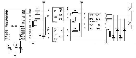
Figure 2 CAN bus controller, bus driver circuit connection diagram
4, CAN bus data recorder software design
CAN bus data logger software design requirements are simple, practical, efficient, and easy to expand. The system program is mainly composed of a main module, a CAN bus controller initialization module, and an interrupt processing module. The main module mainly completes tasks such as initialization of the microcontroller, key value processing, and data display. Among them, the key value processing mainly changes the CAN data receiving baud rate according to the key value; the data display is to display the CAN bus data stored in the external data memory frame by frame.
The CAN bus controller initialization module is used for the initialization of the SJA 1000 bus controller [6]. For example, set the command register (CR) to open receive, error, overload interrupt, set the reset request bit; set the acceptance code register (ACR) and acceptance mask register (AMR); set the output control register to select the output mode and establish the output driver configuration. Wait. For CAN bus data message reception, the acceptance filter is set by writing to ACR and AMR. If a message passes the test of the acceptance filter and the receive buffer has space, the complete message can be received correctly. Passing the filter test means that the message identification code height 8 bits (ID.10~ID.3) and the acceptance code bits (AC.7~AC.0) must be equal, and these bits are the acceptance mask bits (AM. The corresponding bits of 7~AM.0) are masked. That is, if one of the following two equations is satisfied, the message is received.
(ID.10 to ID. 3) = (AC.7 to AC. 0) (1)
(AM.7~AM .0)=11111111B (2)
The purpose of the CAN bus data logger is to receive all messages of the CAN bus data, so the AMR register initialization setting should satisfy equation (2).
The interrupt module identifies different interrupt sources by judging the states of the IR registers and performs corresponding processing. For the receive interrupt, the data received by the receive buffer should be stored in the external data memory, and the interrupt should be immediately jumped out to perform the processing of the main program or wait for the reception of the next frame of data to be interrupted, thereby avoiding the loss of the message.
Whether the CAN bus data logger can smoothly receive CAN data, the design of the initialization module program is the key. Due to the modular programming method, the system program has high efficiency and flexible use, which is beneficial to the upgrade of intelligent measurement and control nodes.
5, CAN bus data recorder application examples
The popular car system CAN-BUS commonly has a comfortable CAN bus, a power CAN bus, etc., taking the comfort system CAN bus as an example to illustrate the use of the CAN bus data logger. The comfort system CAN data transfer has five functions [7]: central door lock, power window, light switch, mirror heating and self-diagnosis function. Before data acquisition, first determine the data transmission baud rate, connect the CAN-L cable to the digital storage oscilloscope, and observe the voltage signal on the CAN-L on the oscilloscope as shown in Figure 3.
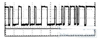
Figure 3 CAN-L voltage signal
As can be seen from the figure, the bit time is 16.0 μs, and the bit rate can be calculated as follows:
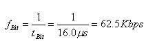
Use the button to set the baud rate of the CAN bus data logger. Connect the recorder test terminals to the CAN-H and CAN-L lines of the CAN bus of the comfort system respectively, and turn on the ignition switch. The received data is shown in Table 1.
Table 1 Data received when the ignition switch is turned on
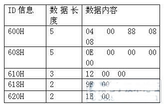
It can be seen from Table 1 that the car comfort system based on CAN bus has the following characteristics:
1. The first position of the IDs of the five nodes is 1, so the comfort system communication data is non-real-time data;
2. The order of the five node IDs from small to large is the central control unit, the left front gating unit, the right front gating unit, the left rear gating unit, and the right rear gating unit. The priority of the network is also the same;
3. The central control unit and the left front gating unit have more control objects, the data length code is 5, the right front gating unit data length code is 3, and the others are 2;
The CAN bus data logger can be used to further collect and analyze other CAN bus data.
6 Conclusion
The portable car CAN bus data recorder has many outstanding advantages: it is suitable for use in the automotive sports environment; it adopts the modular design of general components and software; it can collect the CAN bus data of the car in real time, and the test shows that the system has high working stability. The collected data can be uploaded to the PC through the serial communication interface of the instrument [8], and the data processing and analysis can be completed by using the analysis software of the PC, and the function will be more powerful.
references
[1] Gabriel Leen, Dond Heffernam, and Alan Dunne. Digital Networks in the Automotive Vehicle [J], IEEE Computing & Control Engineering journa1, 1999, (10) 6.
[2] Rao Yuntao, Zou Jijun, Zheng Yongwei. Principle and Application Technology of Fieldbus CAN[M]. Beijing: Beijing University of Aeronautics and Astronautics Press, 2003:22-34
[3] Zou Kuanming. CAN bus principle and application system design [M]. Beijing: Beijing Airlines and Aeronautics University Press. 1996: 30-34
[4] Jinpeng Technology Co., Ltd. OCMJ Chinese module LCD display instruction manual [Z]
[5]Liu Wei. Application of Independent CAN Device SJA1000[J]. Journal of Nanjing Institute of Technology, 2002(1): 33-34
[6]Lü Decai, Ma Feng. Principle and Application of CAN Bus Controller SJA1000[J].Electrical Measurement & Instrumentation,2002(4):57-58
[7] Zhu Jianfeng, Li Guozhong. Principle and Maintenance of Common Cars CAN-BUS [M]. Beijing: Mechanical Industry Press, 2006: 100-102
[8] Wang Jie, Su Donglin, Wang Bingqi. Design of CAN Recorder[J]. Electronic Measurement Technology, 2006(1): 14-15
Jinghongyi PCB: PCBA, PCB Assembly , Printed Circuit Board Assembly Services Provider.
Jinghongyi PCB is a leading PCB manufacturer and assembler in China. It provides one-stop PCB Manufacturing and PCB assembly services, including PCB Prototype manufacturing, small and medium batch manufacturing, and Prototype PCB Assembly Services, Quick Turn PCB Assembly, Low Volume & Small Batch PCB Assembly, Middle Volume PCB Assembly, High Volume PCB Assembly, Turnkey PCB Assembly Service (including PCB production, component procurement, assembly, quality management, etc.), Lead Free PCB Assembly, Multilayer PCB Assembly, LED Lighting PCB Assembly with High Quality, Reasonable Price and Fast Turnover Time Ability.
What Does PCB Assembly Mean?

PCB Assembly Service in China

Although there are many companies in the United States, Britain, India, Australia, Canada, Mexico, Taiwan, Malaysia, Thailand, Germany, Romania and other local selection of PCB assembly manufacturers, but they are not cheaper than assemble in China, because China's PCB assembly cost is lower, better quality.
Why Choose US for PCB Assembly Services - Turnkey, Quickturn PCB Assembly Service

|
Turnkey Services |
Instant Online Quote |
Affordable Pricing |
|
Contact our online customer service or send us an email.
We offer 7*24 hours of online real-time quotation and online customer support. |
We have many years and rich experience in PCB production and assembly. There are very professional technicians and operators, with very advanced PCB assembly process, they are the guarantee of product quality. On this basis, we can also provide you with cheaper, better quality products. |
|
Quick-Turn assembly |
100% Quality Guarantee |
Mature Capabilities |
|
Get the entire PCBA produced in 20 working days from order confirmation to dispatch, including sourcing of parts. However, if you need faster delivery time, we can do it, but you may need to pay an additional premium. |
100% quality guaranteed - free re-work if needed. All parts are sourced from reliable suppliers, and each board undergoes free visual inspection. X-ray inspection, AOI testing, In-Circuit Testing (ICT), and functional testing are also available. |
JHYPCB's assembly lines are fully compliant with IPC-A-610F, are capable of SMT, through-hole and mixed assembly, and can solder BGA and fine-pitch components from 0.38mm pitch. PCB types include rigid, flexible, rigid-flex and aluminum boards. |
|
Prototype, Small or Large Batch |
Sourcing Options |
Considerate Customer Service |
|
Whether you need prototype PCB assembly or bulk assembly, JHYPCB can cater for as little as a single piece 1 to 10000 pieces and has dedicated assembly lines for both low and high volume needs. |
We can source components from reputable distributors, or you can choose from us. These parts are cheaper and can reduce the entire PCBA production time to 7 working days. |
Every PCBA order is assigned a project manager to assist you with the order process. The engineering and assembly teams will also communicate any issues with you to ensure your order proceeds as planned. |
PCB Assembly Capabilities

-
Prototype PCB Assembly as Quick as 1 Day
Our printed circuit board assembly service is North America's leading one-stop solution for PCB and assembly under one roof; specializing in small and medium runs with fast lead-times and no minimum quantity requirements.
-
A Seamless Process from PCB fabrication to PCB Assembly
All printed circuit boards assembled by Advanced Circuits are made by Advanced Circuits and we maintain full control of the entire process so you don't have to manage multiple vendors. When you choose Advanced Circuits, you can be sure that your PCBs flow directly into our in-house Assembly Department to begin assembly without delay.
-
Assembly Types
-
Surface Mount (SMT) Assembly
We are capable of small volume SMT prototyping PCBs with both automated and manual assembly.
-
Ball-Grid-Array (BGA) Assembly
We are equipped with advanced automated BGA placement equipments as well as X-ray inspection equipments to guarantee the quality of BGA assembly.
-
Through-Hole Assembly
Components are placed by inserting leads into holes that covered with solder.Both automated and manual through-hole assembly are available.
-
Mixed Assembly
Both SMT and Through-Hole components will be placed on the PCBs.Single or double side mixed assembly is available.
-
Kit Assembly
PCB Types for Assembly
- Prototype PCB Board
- FR4/ Rigid PCB Board
- Aluminum PCB Board
- LED PCB Board
- Flexible PCB Board
- Rigid Flex PCB Board
- Solder Types
Lead-Free (RoHS compliant)
- Assembly Time
From 8 hours to 72 hours once all parts are ready
- Component Types
- Ball-Grid-Arrays (BGA) of 0.25mm pitch with x-ray testing
- Passive components as small as 01005 (0402) package
- Fine-pitch components as small as 0.38mm pitch
- Test Types
- Visual Inspection
- X-Ray Inspection
- AOI Testing
- In-Circuit Test
- Functional test
- Component Suppliers
- More than 10,000 in-stock components (OPL)
- Digikey, Mouser, TME, Element 14 and more-
- PCB Assembly Testing Capabilities Learn More
| Category | Product Function | Test Type | Test Location |
|---|---|---|---|
| MCU |
51 serial MCU AVR serial MCU ARM Cortex M0, M0+, M3 and M4 serial |
IC Programming | Seeed's Fab |
| General |
GPIO Functional Testing Voltage, Electricity Current, Resistance Test, etc. I2C/Uart/SPI/CAN/One Wire/SWD Temperature, Humidity, Atmospheric Pressure etc. ... |
Functional Test | Seeed's Fab |
| Communication |
GSM/WCDMA/LTE GNSS Bluetooth/LE Ethernet NFC 802.11/b/g/n/a/ac ZigBee Sub-1 GHz 315/433/868/915 |
Functional Test | Seeed's Fab |
| Monoboard Computer | BeagleBone, Raspberry Pi, etc. | Functional Test | Seeed's Fab |
| Certification | FCC, CE, GS, TELEC etc. | Regulatory | Accredited Third-Party Lab |
PCB Assembly Applications
 |
 |
 |
 |
|
Aerospace |
Automotive |
Biomedical |
Consumer-electronics |
 |
 |
 |
 |
|
Energy |
Industrial |
Network-computer |
Telecommunications |
PCB Assembly Manufacturing Design Tips

-
Choosing between ROHS (LEAD-FREE) or standard (LEADED) solder
RoHS is used most frequently when shipping to Europe. As RoHS and Leaded solder temperatures are different, boards must either be completely soldered with RoHS or Lead. This includes BGAs. Non-RoHS components can withstand RoHS process. Avoid mixed process; that is, mixed solder. For example, a standard HASL bare board should not use a RoHS assembly process.
-
Water Clean
Aqueous clean process uses water soluble flux during soldering. The board is cleaned using water. This process yields shinier solder joints and an overall cleaner looking PCBA, without any flux residue.Use No Clean Flux only if your PCBA has some parts (batteries, microphones, speakers, relays, etc...) that can be damaged if submerged in a water wash. No Clean Flux leaves flux residue on the finished PCBA; however, flux is non-corrosive and non-conductive.
If a few components are water sensitive, you may choose to have the PCBAs processed with water soluble flux without initially soldering the water sensitive components. Make sure include specific instructions to hand solder these few components after cleaning with No Clean Flux.
-
Silkscreen
-
Placement (X-Y) Centroid Files
If you do not send centroid files with you CAD data, we can extract them for an extra fee.
-
Shortages
-
Fiducial
-
Moisture Procedure
-
Paste Layers
-
Multi-part Assembly orders
-
Substitutions
PCB Assembly Cost

PCB Assembly Cost = PCB manufacturing cost + PCB frame test or flying probe test fees + PCB engineering cost (only for small prototype order) + Component cost (additional 5%) + SMT assembly charges + PCB assembly test cost + Box building charges + Package cost (for special application) + Logistics cost (requested)
PCB Assembly Process

PCB Assembly Process

PCB Assembly Process Flow Chart
Things Needed for Printed Circuit Board Assembly
Following electronics parts and consumables are needed for PCB assembly
- Printed Circuit Board
- Electronic components
- Soldering materials including solder wire, solder paste, solder bar, solder preforms (depending on the type of soldering to be done)
- Soldering flux
- Soldering equipment including soldering station, wave soldering machine, SMT equipment, inspection and testing equipment etc.
Once all of the above equipment, electronic parts and all raw materials are arranged, it is time to start the printed circuit board assembly process.
1. PCB Manufacturing
PCB design & fabrication helps you with experienced PCB design and fabrication, high accuracy, quality control. In general, your PCB prototype can be well served by us. PCB Assembly includes layout, fabrication and assembly. We also have monthly abilities of offering 35,000 square meters PCB, 80 million point SMT and introduce ICT, flying probe, AOI, X-ray, function test, burn-in test into inspection phase. We can help you with a system of transforming natural resources, raw materials and components into a finished product that is delivered to the end customer and strive to have the most optimized supply chain to make efficient and costs lower.
2. Screen Printing of Solder Paste onto PCB Board
loctite solder pastePhysicochemical and process property of solder paste directly impact SMT soldering quality. Solder paste printing is applicable for placing appropriate amount solder paste onto PCB pads, in order to ensure good circuit connection between SMT components and PCB pads and their mechanical strength. Solder paste printing is the critical process of SMT. Metal template printing is conventionally applied so far. According to related statistics, 60%~70% quality problems are caused by solder paste printing in premise of quality guarantee of components and printed circuit board. Requirements of solder paste printing:
a. Place solder paste appropriately, evenly and uniformly. Solder paste shape is clear and neighbor shapes do not connect. Solder paste shape is in compliance with that of pad, without any dislocation.
b. In general, the unit area solder paste amount should be 0.8mg/mm2, particularly 0.5mg/mm2 for narrow-pitch components.
c. After solder paste printing, the shape has no heavy collapse and edges are trim. Plate surface is not allowed to be contaminated by solder paste.
There are a large variety of solder paste with different alloy compositions, granularity and viscosity even for all from one manufacturer. How to choose appropriate solder paste highly impacts the product quality and cost. Now NOD Electronics is using Loctite lead free solder paste. We have figured out Loctite solder paste is reliable to ensure good product quality after process engineering test of its printability, demoulding, thixotropy, cohesiveness, wettability, welding spot defect and residue.
3. Lead-free PCB Assembly
In light of environmental concerns and customer request, we can offer lead-free PCB board assembly which complies with RoHS standards. At upstream, we choose PCB laminates in compliance with RoHS standards for PCB manufacturing. Also we use lead free solder paste and related reflow/wave ovens. We strictly fulfill RoHS requirements in light of your local regulations and don`t want to make you into any trouble on this basis.
4. Burning Program and In-Circuit Test (ICT)
Our test engineers will check short circuit, voltage, current, signal transmission of PCB assembly boards according to your ICT test plan. A professional report will be handed up to you if for any detected problems. For batch order, we design exclusive test frames to fast the ICT test process. We are also well sophisticated with decoding and burning program for you. Related test frame will be built to ensure products work effectively according to your requirements.
PCB Assembly Requirement List
| No. | Types Of Assembly | File Format | Component Footprinr | Component Package | Testing Produres | Produres | Others |
| 1 | SMT ASSEMBLY | Gerber RS-274X | 0201,0402,0603- | Reels Package | Visual Inspection | Lead-Free(Rohs) | Custom Reflow Profile |
| 2 | SMT & THT Assembly | BOM(.xls,.csv,.xlsx) | BGA,QFN,QFP,PLCC | Cut Tape Package | X-Ray Inspection | Leaded Solder | Standard Reflow Profile |
| 3 | 2 sided STM,THT Assembly | Pick-N-Place/XY file | SOIC,POP...Connectors | Tube and Tray | AOI,ICT(In-Circuit Test) | Reflow Soldering | Smallest Size:0.2"x0.2" |
| 4 | Mixed Assembly | - - | Small Pitch of 8 Mils | Loose parts and bulk | Functional Testing | Wave Soldering | Largest Size:15"x"20 |
Find Out More
Flexible PCB Circuit Board Assembly
Through Hole Technology Assembly
Mixed Technology PCB Assembly
Double Sided PCB Assembly
Learn More Information
How to Mixed Technology PCB Assembly
Comparison between THT Assembly and SMT Assembly
How to start to Prototype PCB Assembly
Introduction About Single-sided and Double-sided SMT Assembly
How to ensure a smooth PCB assembly
How to Reduce PCB Assembly Cost
PCB Assembly Service
Printed Circuit Board Assembly, PCB Assembly Service, PCB Assembly
JingHongYi PCB (HK) Co., Limited , https://www.pcbjhy.com