Phosphorescent materials that can be used in white O LEDs have three primary colors of blue, green and red. Although yellow and orange are not one of the three primary colors, they can be matched with dark blue because of yellow, or blue or sky blue for orange, and white light of two colors is mixed.
The judgment of each color or color saturation is distinguished by 1931 CIEx, y color coordinates (see Figure 4-13).
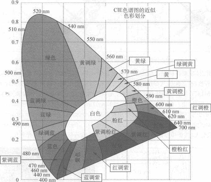
1931CIEx, y color coordinate color division example diagram
In the case of a green light color, a substantially x coordinate value of less than or equal to 0.3 can be regarded as green. The y-coordinate value is an indicator of color purity, such as Ir (ppy)3 and (ppy)2Ir(acac) OLED 1931CIEx, the y color coordinates are (0. 27, 0.63) and (0. 31, 0. 64) (The phosphorescence spectrum is λmax, 510 and 525 nm, respectively). It can be said that Ir (ppy)3 is a relatively green material, but it is relatively green (py) zIr (a little yellowish green relative to the former). Acac) its color (yellow-green) saturation is higher.
Therefore, for those green phosphorescent materials, its 1931CIEx, yx coordinate value is 0. 33, 0.34, 0. 35, even to 0. 40 or more than 0. 40, usually called yellow-green phosphorescent material.
Yellow is the middle color. It is impossible to say a clear range. You can only select ((0. 50, 0. 50) coordinate values ​​as the saturated yellow 1931CIEx, y coordinate value. The smaller the x coordinate value, the closer to yellow-green; The larger the x coordinate value, the closer it is to orange.
Compared with the condition of the green phosphorescent material, if the 1931 CIEx, the y color coordinate two values ​​are 0. 50 small too much (about less than 0. 45), such materials will be considered as yellow-green phosphorescent materials, will not be listed for discussion. Orange is also a middle color, can not say a clear range, if a lot of red phosphorescent material color is slightly insufficient, the color will fall in the orange place, roughly can be fixed ((0. 60, 0. 40) The coordinate value is taken as the saturation orange 1931CIEx, y coordinate value.
The orange color is sandwiched between yellow and red. 1931CIEx, the y coordinate is shifted to the left ((the value of x becomes smaller, the value of y becomes larger) becomes yellow, and the rightward deviation (the value of x becomes larger and the value of y becomes smaller) turns red.
How to define yellow and orange or orange and red is different from person to person.
Distinguish whether the color of the phosphorescent material is green, yellow or orange. If the OLED 1931CIEx, y is not marked and cannot be known, then the color of the illuminating wavelength can be roughly judged to predict its possible color. See the example of Figure 4-14. .
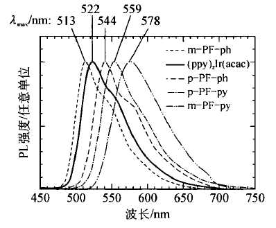
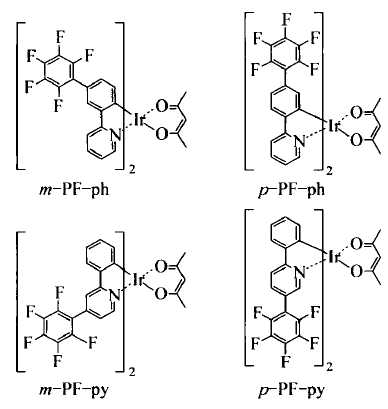
Phosphorescence spectrum of Ir coordination complex from green light to orange light distribution
At present, there are 50 kinds of OLED materials that have been reported to emit red phosphorescence. Since the discovery of OLED organic phosphorescent materials in the late 1990s, the development of blue phosphorescent materials has always lagged behind red and green light. Phosphorescent materials have so far rarely achieved color purity like deep red or dark green.
Even in dark blue with high color purity, the effect of making an OLED is often not unsatisfactory, that is, the material (also causing the device) has a short life. In order to produce a white OLED with satisfactory performance, the current choice is mainly a sky blue phosphorescent material, which requires that the red phosphorescent material to be matched is close to the saturated red dark red.
Therefore, the requirements for color purity of red phosphorescent OLED materials have to be raised very high, otherwise the white OLEDs produced cannot be close to positive white.
The earliest appearance in OLEDs as a phosphorescent material is PtOEP, an organic phosphorescent material that emits a deep red color and is nearly saturated red. The wavelength of red light emitted by PtOEP is both long and narrow.
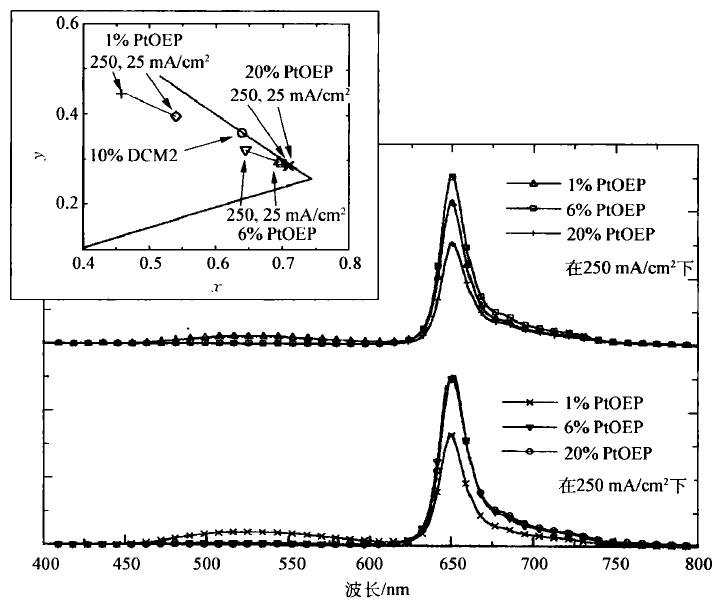
Electroluminescence Spectra of PtOEP Red Phosphorescent OLED and Its 1931 CIEx, y Color Coordinates
The appearance of this material in OLEDs was due to the red material of the OLED (in the late 1990s).
The lowest energy absorption wavelength of PtOEP is about 540 nm, and the observed phosphorescence wavelength is at 650 nm (the weaker vibrational electronic harmonics are multiplied at 623, 687, and 720 nm). This phosphorescence wavelength is quite narrow (half-wave width is only about 20 nm) and the absorption of the lowest energy from PtOEP has a Stokes shift of more than 100 nrn.
It is reported in the literature that the fluorescence position of PtOEP is about 580 nm, and there is obviously a small Stokes shift, which indirectly proves that the luminescence at 650 nm is phosphorescence rather than fluorescence. In addition, the experimentally measured PtOEP has a phosphorescence lifetime of about 80 μs at room temperature in solution, which is significantly longer than the fluorescence lifetime of general organic materials of about ns.
These spectral physics data point to the luminescence at 650 nm PtOEP is phosphorescence rather than fluorescence. PtOEP in the solution state at room temperature phosphorescence about 0. 45.
The device efficiency drops rapidly as the current density increases (or the O LED brightness increases), a phenomenon commonly known as "efficiency roll off."
For example, the OLED produced by Facially encumbered Pt porphyrins has a device current density of about 0. When 1 mA/cm2 (or brightness is about 3 cd/m2), ?ext reaches about 8.2% of the highest point, but at a brightness of 100 cd/m2 (about 6 to 7 mA/cm2)? About 7%; when the brightness is 500 cd/m2 (this is only half of the brightness required for white light illumination), the current density has reached 300-400 mA/cm2, and the ext is less than 1%. This is worse than the performance of red fluorescent materials.
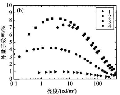
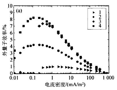
Facially encumbered Pt porphyrins OLED's luminous power efficiency and current density and brightness
A study of PtOEP red phosphorescent materials found that "efficiency roll-off" has a lot to do with the length of phosphorescence. The phosphorescent lifetime of PtOEP red phosphorescent materials is too long (or not short enough), resulting in a greater chance of self-quenching of the triplet state of the material in the device, especially at higher current densities.
In order to improve the deficiency of PtOEP red phosphorescent materials, the earliest (btp)2Ir(acac) proposed by Thompson and Forrest research team has a phosphorescence lifetime of about 6μs and a Φp of about 0.2.
Under a similar OLED device structure, at a reasonable current density of 10 mA/cm2 (typically at this current density, the device has a minimum brightness that can be used), PtOEP's ?ext is 1.9%, and (btp ) 2Ir(acac)?ext is 3. 7%, nearly twice as high as PtOEP, and the “efficiency roll-off†is somewhat relieved.
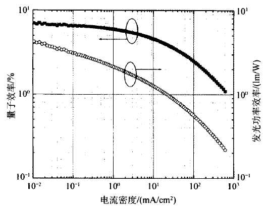
(btp)2Ir(acac) diagram of luminous power efficiency and current density of red phosphorescent OLED
After (btp)2Ir(acac), the Cannon R&D team and the Liu Ruixiong research team at Tsinghua University in Taiwan proposed new red phosphorescent materials Ir (piq)3 and (piq)2Ir(acac), respectively.
Both use 1-phenylisoquinoline (piq) as a ligand for the cyclometalation of Ir, except that the former Ir(piq)3 is a homozygous Ir coordination complex, the latter (btp)2Ir ( Acac) is a ligand heterozygous Ir coordination complex.
In fact, piq is a very good chemical structure for red-emitting phosphorescent ligands. Most of the red-phosphorus cyclometalation ligands developed later are derived from the parent chemical structure of piq.
When the brightness of the OLED increases ten times, the ?ext of Ir(piq)3 drops to about 8.5% (1000 cd/m2); the ?ext of (btp)2Ir(acac) drops to about 7.0% (about 400 mA/ Cm2, 25 000 cd/m2). This "efficiency roll-off basically conforms to Ir(piq)3 and (btp)2Ir(acac) is not a very long phosphorescence lifetime of 0.7 to 1.1 and 1.65 μs.
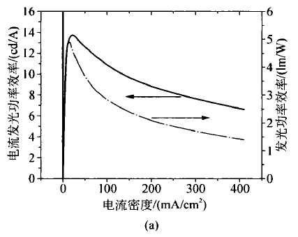
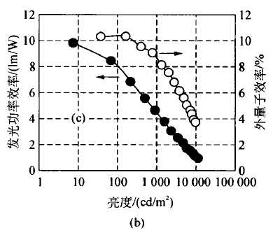
Relationship between luminous power efficiency and current density of red phosphorescent OLEDs
(a) (btp) 2Ir (acac) production (b) Ir (piq) 3 production
The Cannon R&D team later published a red-emitting phosphorescent O LED made in Ir(4F5Mpiq)3 in 2005 with a 1931 CIEx, y color coordinate (0. 66, 0.34).
The red color purity is slightly inferior to Ir(piq)3 or (btp)2Ir(acac), but the device ?ext can be up to 15.5 0 o (or ?p12.4 lm/W), which is the brightness of the device. It was obtained at 218 cd/mz (or 1.23 mA/cm2 current density).
Basically, this device still exhibits an "efficiency roll-off" phenomenon: when the brightness of the device increases to more than 10 000 cd/m2 (or the current density increases to nearly 120 mA/cm2), the device's best is reduced to 7.9%. (or ?p 3.7 lm/W).
With so many red phosphorescent OLED materials, the performance of the device is affected by the chemical and physical properties of the luminescent material itself, but another device that affects the performance of the device is the solution process or the dry process and the device selected in the device. The host material with the dopant.
The two widely used red phosphorescent dopants are exemplified by (btp)2Ir(acac), (piq)2Ir(acac).
In 2005, Taishi Tsuji developed OLEDs doped with different host materials (btp)2Ir(acac).
ITO/NPB/host material doping (piq)2Ir(acac) / Alq3 /Li2 O/Al, where the host material is Alqa, BAIq, BCP or OXD-7, in which BAIq with electron transport properties is when the host material optimum performance, device life is also longer than 4 times in BCP as the main material of the device.
The other is an OLED produced by a solution process reported by Academician Cao Pu of South China University of Technology: ITO/PEDOT: PSS/PVK/blends/Ba/Al. Here, the blends are three different polymers PFO, PVK, and PFTA mixed with PBD or TAZ electron transport materials as the host material.
Among them, the main material of PFTA mixed PBD is the best, and the ext is up to 1200, which is more than the EXT of the OLED produced by the dry process (vacuum evaporation) reported by Cannon. 3% is higher.
In addition, Ma Dongge of the Changchun Institute of Applied Chemistry of the Chinese Academy of Sciences and Yang Chuluo of Wuhan University used a new main material O-CzOXD vacuum evaporation to produce a red phosphorescent OLED, which was upgraded to 18.5%. The same progress occurred on the Ir(4F5Mpiq)3 reported by Cannon: Yang Yang made ITO/PEDOT by wet process: PSS/PFO: Ir(4F5Mpiq)3/CsZ C03 /Al OLED, the highest?P from the original 12. 4 lm/W increased to 17. 6 lm/W.
In order to verify the importance of the red phosphorescent OLED host material and the hole transport layer (HTL), (fppz) 2 Os ( PPhMe 2 ) 2 and ( fptz ) 2 Os ( PPh 2 Me ) 2 , the doping of these two Os heavy metals The materials are made into OLEDs and have been reported many times, with the most prominent latter: ITO/HTL/Host: (fptz)2Os( PPh2 Me)2 /HBL/LiF/Al, its luminous power efficiency has reached new heights. .
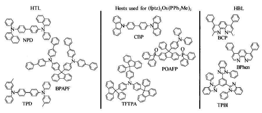
Hole transport layer (HTL) material, host material and hole blocking layer (HBL) material used in combination with (fptz)2 Os( PPh2Me) 2
When first reported, the HTL was NPB or BPAPF; the host material was CBP; and the HBL was BCP (bathocuproine). When the dopant mass fraction is 20% (the OLED has just reached the red color purity) and the device is at a current density of 20 mA/cm2, ?ext is 11.5% (NPB is HTL) or 13.3% (BPAPF is HTL). The second time it was reported, the HTL was NPB; the bulk material was changed to TFTPA.
When the dopant mass fraction is 21% device?ext up to 180o<r}p up to 25 lm="" w). What's hard to get is that this device has only a slight "efficiency roll-off" phenomenon. Under 1000="" cd="" m2 illumination brightness? ext="" has hardly changed, ?p only slightly drops to 22="" w ( See Figure 4-25). Even with an ultra-high illumination of 10000="" mz (current density is less than 10="" ma="" cm2), }p still has 15="" w.
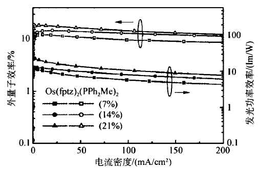
(fptz)2Os (PPh2Me)2 luminescence power efficiency and current density diagram of red phosphorescent OLED
(fptz) The highest luminous power efficiency of 2Os (PPh2 Me)2 red phosphorescent OLED was refreshed by Xu Qingfeng of Taiwan's Hsinchu Jiaotong University and Tsinghua University of Taiwan.
The HTL in the device is the TPD host material is a bipolar POAPF, which in turn is a new host material HBL is Bphen.
This time, the highest?ext reached 19.9% ​​(or ?P up to 34.5 lm/W). The illumination brightness of the device at this highest luminous power efficiency is about 100 cd/m2. The high luminous power efficiency mentioned in the report can be attributed to the good charge balance in the device, which is a large part. The reason is that the host material used in the device is bipolar.
The “efficiency roll-off†phenomenon of the device is also very slight: 18.6% at 1000 cd/m2 illumination. There is still 26.1 lm/W. (fptz) The phosphorescence wavelength of 2Os (PPh2 Me)2 is slightly shorter than 617 nm, which helps the material to avoid the "efficiency roll-off" at high current densities.
Why (fptz)2Os( PPh2 Me)2 can stand out from many red phosphorescent doping materials?
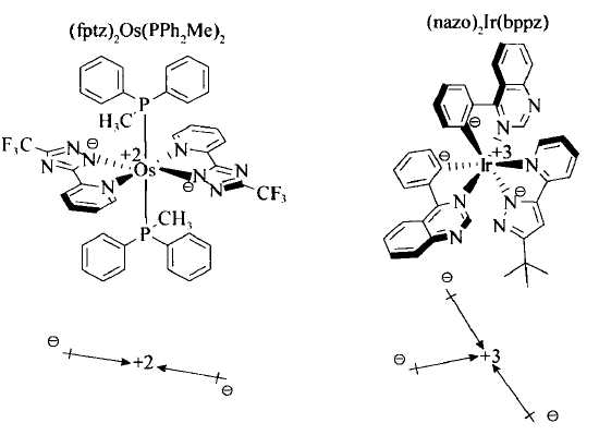
The advantage of (fptz)2Os(PPh2Me)2 is that the red color purity of the doped OLED is very stable and is not affected by the change in the doping mass fraction. This is followed. (fptz) 2Os( PPh2 Me)2 is related to the molecular symmetry structure itself.
A symmetrical molecule itself does not have a molecular dipole moment, which is different from most red phosphorescent dopants.
When a molecule without a dipole moment is mixed with other molecular materials in the solid state, the polarity of the environment does not change with the change of the doping mass fraction, and the energy gap of the molecule itself (the wavelength of the emission) does not change with the polarity of the environment. And change.
Suizhou simi intelligent technology development co., LTD , https://www.msmvape.com