How to ingeniously rectify the circuit and debug the detection circuit?
After completing a project, many engineers found that most of the time spent on the entire project was spent on debugging the circuit to correct the circuit. Pay attention to the following details and you will save the circuit.

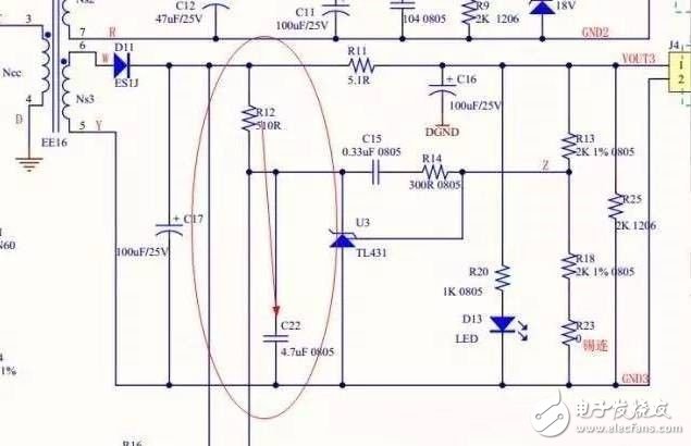
(1) In order to obtain a feedback circuit with good stability, it is usually required to use a small resistor or choke outside the feedback loop to provide a buffer for the capacitive load.
(2) The integral feedback circuit usually requires a small resistor (about 560 ohms) in series with each integrating capacitor greater than 10pF.
(3) Do not use active circuits outside the feedback loop to filter or control the EMC RF bandwidth, but only passive components (preferably RC circuits). The integral feedback method is effective only when the open loop gain of the op amp is greater than the closed loop gain. At higher frequencies, the integration circuit cannot control the frequency response.
(4) In order to obtain a stable linear circuit, all connections must be protected using passive filters or other suppression methods such as opto-isolation.
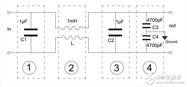
(5) Use an EMC filter, and the IC-related filters should be connected to the local 0V reference plane.
(6) Input and output filters should be placed at the connection of the external cable. Any wire connection inside the shielded system is required for filtering because of the antenna effect. In addition, filtering is also required at the wire connections inside the shield system of the converter with digital signal processing or switching mode.
(7) High quality RF decoupling is required on the analog IC's power and ground reference pins, just like digital ICs. However, analog ICs typically require low frequency power supply decoupling because the power supply noise rejection ratio (PSRR) of the analog components increases little after being above 1 kHz. RC or LC filtering should be used on the analog power traces of each op amp, comparator, and data converter. The corner frequency of the line filter should compensate for the PSRR corner frequency and slope of the device to achieve the desired PSRR over the entire operating frequency range.
(8) For high-speed analog signals, transmission line technology is necessary depending on the connection length and the highest frequency of communication. Even with low frequency signals, the use of transmission line technology can improve its immunity to interference, but transmission lines that do not have the correct match will have an antenna effect.
(9) Avoid using high-impedance inputs or outputs that are very sensitive to electric fields.
(10) Balanced transmit and receive (differential mode) techniques are used in analog circuits since most of the radiation is generated by common mode voltages and currents, and because electromagnetic interference in most environments is a common mode problem. Will have a good EMC effect and can reduce crosstalk. The balanced circuit (differential circuit) drive does not use the 0V reference system as the return current loop, thus avoiding large current loops and thus reducing RF emissions.
(11) The comparator must have hysteresis (positive feedback) to prevent erroneous output changes due to noise and interference, and to prevent oscillation at the trip point. Do not use a comparator that is faster than needed (keeping dV/dt within the required range, as low as possible).
(12) Some analog ICs are inherently sensitive to RF fields, so it is often necessary to shield such analog components using a small metal shielded box mounted on the PCB and connected to the ground plane of the PCB.
Gel Battery,Gel Cell Battery,Gel Battery For Car,Gel Type Battery
SUZHOU DEVELPOWER ENERGY EQUIPMENT CO.,LTD , https://www.fisoph-power.com