This article highlights the M.2 Series Next-Generation (NGFF) connector for original equipment manufacturers (OEMs), which uses new interface standards for smaller form sizes and capacities to improve data transfer. Speed ​​and save space on printed circuit boards (PCBs). In addition, in response to current and future market demand for ultra-thin solutions, M.2 (NGFF) products are designed for a wide range of applications, helping original equipment manufacturers meet challenges and provide consumers and businesses with newer, smaller, and Faster device.
Today, consumers and businesses around the world want to build more connections in the connected world. No matter where you are or what kind of career you are in, people always want new, smaller and faster equipment to help them easily achieve this. Clearly, original equipment manufacturers (OEMs) and component manufacturers are facing unprecedented challenges – how to design and develop devices with these features.
Industry leaders have made important contributions to this and are working to develop a variety of interconnect solutions to help OEMs meet the challenges. For example, module cards, expansion cards, and other functions for wireless Wi-Fi, WWAN (Wireless Wide Area Network), Bluetooth, GPS, and Solid State Drive (SSD) for PCs, laptops, tablets, and game consoles.
In the PCI-SIG industry standards organization, the M.2 (Next GeneraTIon Form Factor or NGFF) connector has spurred the development of the previous generation of PCI Express mini-card connectors. In order to meet the development characteristics of OEM equipment, M.2 connectors are designed with both speed and space in mind.
The M.2 connector is designed to increase data transfer speeds to meet the latest industry specifications such as PCI Express 3.0, USB 3.0 and SATA 3.0. The high-speed energy of the M.2 connector is optimized for the upper and lower contacts. The signal is transmitted back and forth between the printed circuit board (PCB) contacts (point A in Figures 2 and 3) and the module card contacts (point B in Figures 2 and 3).
The PCI Express (PCIe) Mini Card connector features a press-contact design with a large metal surface (red oval in Figure 2) that secures the contacts in the housing. Since these metal materials are not on the straight path of A to B (or B to A), they are called signal pins. Signal pins increase the capacitance of the area, create noise coupling, and reduce high frequency contact performance.
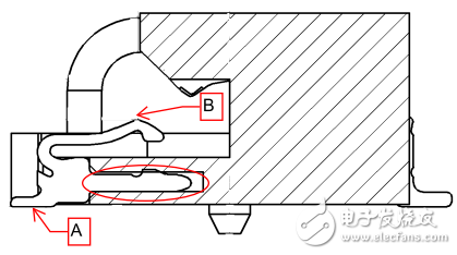
Figure 2 - PCI Express Mini Card Lower Contacts
The M.2 connector (shown in Figure 3) uses crimp-formed contacts without large-area signal pins. The linear signal path optimizes the capacitance of the entire signal trace and improves performance.
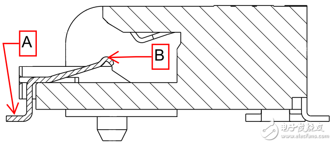
Figure 3 - M.2 connector 3.2H lower contact
By comparing the differential insertion loss plots, it can be seen that the insertion loss of the PCIe mini-card connector intersects at -2 dB around 6.75 GHz (as shown in Figure 4), while the M.2 connector remains below -2 dB until the frequency reaches 12 GHz. (Figure 5), this is enough to support the latest specifications of PCIe 3.0, USB 3.0 and SATA 3.0.
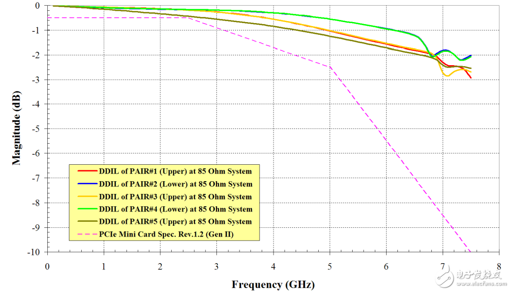
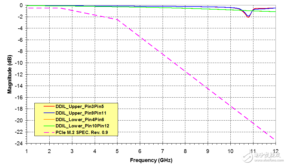
Figure 4-85 Differential insertion loss of PCI Express mini-card connector under Ω Figure 5 - Differential insertion loss of 2.25H for M.2 connector under 85 Ω
The M.2 connector also saves space. The 0.5 mm pitch of the M.2 connector is sufficient to save more than 20% of the PCB space compared to the 0.8 mm pitch of the PCIe Mini Card connector. The connector height has also been reduced from less than 4 mm to 2.25 mm for single-sided module cards. The M.2 connector height of the duplex module card has been reduced to 3.2 mm, which is 20% lower than the PCIe Mini Card.
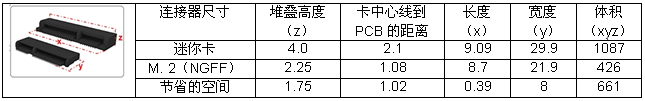
Figure 6 - Comparison of Mini Card Connector and M.2 Connector
The current M.2 connector uses a three-step bevel insertion method. This method (shown in Figure 7) has two advantages. First, the PCB space at the insertion of the module card is increased. The module card is fixed at a 25° angle, allowing for higher height components to be placed near the insertion area, helping OEMs save space and increase design flexibility. If the module card is fixed in parallel with the motherboard, too high a component may affect the insertion path. Secondly, this module card insertion method is more convenient for the staff to operate. Due to the need for manual insertion, the operator's hand position is higher than the motherboard to reduce the risk of damage to the motherboard components.
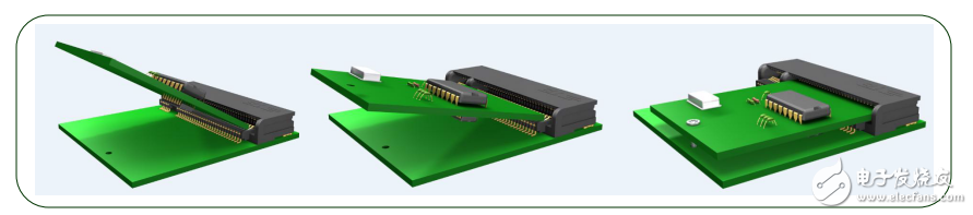
Figure 7 - Three-step insertion method
Whether in the connector as a "car tire" or in a module card as a "car engine", the performance and benefits of the M.2 connector are well known. Since the module card market for the M.2 connector platform is still in its infancy, the limitations of the connector's performance may not be fully discovered. As the modular card market continues to evolve, the superior performance of the M.2 connector may decouple it from the PCIe mini-card connector platform.
About the Author:

Brian Long is a Field Application Engineer at TE ConnecTIvity Consumer Electronics in Harrisburg, PA. He has more than 7 years of experience in the connector industry, including product development, manufacturing and application engineering. Long graduated from Rochester Institute of Technology with a bachelor's degree in mechanical engineering and a master's degree in business administration.
----------------------------
More connector technology hot text can be accessed in the special issue page for free download: "Connector Technology Special Issue"

Product Name: Car Charger
Place of Origin: Guangdong, China (Mainland)
Brand Name: OEM
Output Type: DC
Connection: Other
Rated Voltage: 12V-24V
Working Temp: 0-55℃
Weight: 36g
Materials: PC+ABS
Color: White Black
Warranty: 1 year
Suitable for:Most digital devices
SMART PROTECTION & ATTRACTIVE DESIGN ------ Intelligent circuit design protects against short circuiting,over-heating,over-current,and over-charging. Charging stops when battery is full. Car charger with blue LED indicator,which makes it convenient to find exactly where the connection should go; And the light is soft enough not to distract at night.
Dual USB Car Charger Adapter,USB Smart Port Charger ,Car Charger,USB Car Charger For Phone
Shenzhen Waweis Technology Co., Ltd. , https://www.waweis.com