The realization of wireless network video QoS platform based on NS-2
1 Introduction With the rapid development of wireless network technology, the business volume of wireless multimedia communications will far exceed the traditional business. Video services, especially real-time video services will be the main body of wireless network services in the future, so the problem of video QoS guarantee for wireless networks has become a new research hotspot. In the research process of QoS guarantee mechanism, due to the complexity of the network and the constraints of economic conditions, network simulation technology is very important. Network simulation technology establishes statistical models of network devices and network links, and simulates the transmission of network traffic to obtain network performance data required for network design or optimization.
Based on the analysis of the EvalVid tool set, combined with the NS technology, a method for establishing an image QoS research simulation platform in a wireless network using NS-2 is proposed. NS supports a wide range of protocols and uses an open architecture. It is easy for users to develop new protocols according to their needs. Therefore, it is very appropriate to use NS to study network transmission strategies and transmission performance for specific wireless video services.
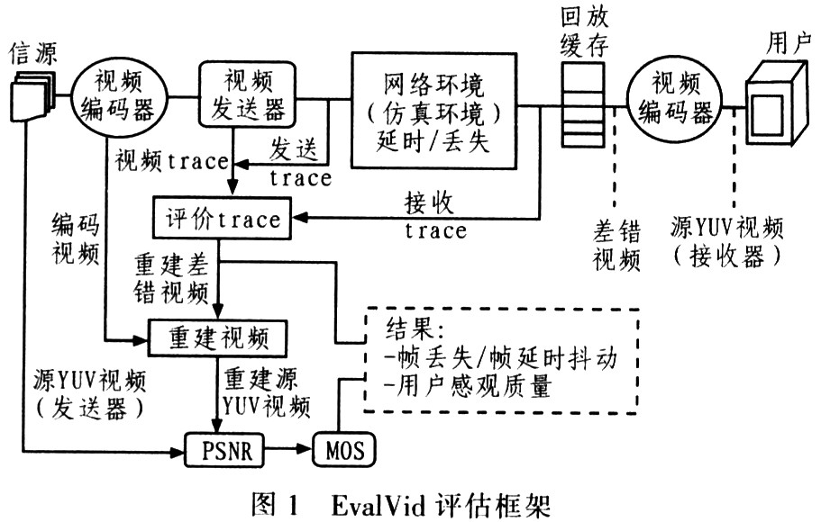
2 QoS research of network video Jirka Klaue gives a framework and tool set EvalVid for unified evaluation of video transmission quality. EvalVid has a modular structure, which can realize the interaction between the networks through trace files under the video encoding strategy used. It is easy to use in any network environment. The EvalVid evaluation framework is shown in Figure 1.

(1) The source video source may be YUV video information in QCIF (176 × 144) or CIF (352 × 288) format.
(2) The video encoder and decoder are used to encode and decode YUV video to adapt to the network transmission. The encoding strategy can be MPEG, H. 261 etc.
(3) The video transmitter VS generates trace files from the encoded video files, that is, video trace files and send trace files. VS reads the compressed video file output by the video encoder and divides the large video frame into smaller segments for transmission via UDP packets in the network environment. Send a trace file to record the UDP packet timestamp, packet id and packet load size of each transmission. The video trace file records the information of each frame in the video file. The video trace file and the sent trace file are used in the subsequent video quality assessment.
(4) The evaluation trace uses information such as packet timestamp, packet id, and packet load size recorded in the original encoded video file, video trace file, sending trace file, and receiving trace file. ET generates a frame / packet loss, frame / packet delay Time jitter report and a reconstructed video file.
(5) The digital video quality evaluation of the reconstructed video is realized by frame-by-frame comparison. If the selected codec cannot handle the lost frames, the error concealment technique of each lost frame is replaced by inserting the most recently decoded frame.
(6) Subjective and objective quality evaluation (PSNR, MOS) Subjective quality evaluation directly reflects the perception of human eyes, and is a relatively accurate method of image quality evaluation. Commonly used indicators are based on the average opinion score (MOS score) of the 5-level quality system or the 5-level injury system. The objective evaluation of video image quality is measured by certain mathematical criteria, and the peak-to-peak signal-to-noise ratio (PSNR) is commonly used. Its definition is as follows: 
In the formula, M and N are the dimensions of the width and height of the video frame; x (i, j) and x '(i, j) are the brightness or chromaticity of the original and reconstructed pixels at (i, j) value.
Chih-Heng Ke et al. Combined EvalVid and NS-2 to give a new tool set for video stream quality assessment. The combination of NS-2 and EvalVid is realized through three connection simulation agents, namely MyTrafficTrace, MyUDP and MyUDPSink. Designing these interfaces requires both reading video trace files and generating data for video transmission quality evaluation.
The MyTrafficTrace agent extracts the frame type and frame size of the video trace file from the VS output file. In addition, the agent divides the video frame into small segments and sends these segments to the lower layer UDP at the appropriate time. The sending time is set by the user in the simulation description file.
MyUDP is an extension of UDP proxy. This new agent allows users to specify the output file name for sending traces. It records the timestamp, packet id and packet size of each transmitted packet.
The tasks of the MyUDP agent correspond to the tasks of the cp-dump or win-dump tool in a real network environment. MyUDPSink is a receiving agent that receives the video frame packets sent by MyUDP. This agent also records the timestamp, packet id and load size of each received packet in the file specified by the user. Based on this expansion, a quality evaluation system suitable for wireless video transmission is proposed.
3 Implementation of wireless network video QoS platform based on NS-2
3.1 The wireless module in NS-2 The wireless module in NS was originally introduced to NS by CMU's Monarch working group. The wireless module introduced by CMU / Monarch can be used for pure wireless network simulation. The expanded wireless module also supports wireless and wired network co-simulation and mobile IP. There are some other wireless modules available in NS-2, including Blueware, Blue2Hoc, Mobiwan, GPRS, CIMS, etc. The wireless module uses MobileNode as the basic core, and supports some multi-hop Adhoc network and wireless LAN simulation through some additional features. MobileNode adds the functions required by wireless and mobile nodes from the basic Node, and can set its various network components in OTCL, such as link layer (LL), ARP module connected to LL, interface queue (ifql, ifqlen) MAC layer And network interfaces. The mobile node is connected to the wireless channel through the network interface. The ad-hoc routing protocols currently supported by MobileNode include DSVD, DSR, TORA and AODV.
3.2 The process of wireless network video simulation As in the simulation of video transmission, the real video stream needs to be transmitted in the network, it is necessary to expand and modify NS-2 to add the network elements required for the video transmission simulation process, including Agents, namely MyTrafficTrace, MyUDP and MyUDPSink. If the researcher wants to verify his proposed transmission strategy, he needs to use C ++ and OTcl to program the network element, add his proposed strategy to the network element, and then recompile the NS. After completing the expansion of NS-2, you can use NS for simulation. The process is as follows:
(1) Use the selected video encoder to encode the original video, and extract the relevant information of the video packet from it, write a program to generate a trace file for transmission. The format of the trace file is <packet sequence number, time stamp, packet size>.
(2) Set the basic properties of the physical layer (MAC layer) according to the characteristics of the real network under study; establish various nodes and configure their parameters to set the motion characteristics of the nodes; configure the network topology and determine the basic link Features such as latency, bandwidth, and selection strategy.
(3) Establish a protocol agent, bind the protocol agent to the corresponding node, establish the connection between the agents; determine the distribution of traffic on the network, and bind the video traffic and various background traffic to the corresponding protocol proxy on.
(4) Set the Trace object. The Trace object records the specific types of events that occurred during the simulation process in the trace file. NS-2 saves the entire simulation process through trace files. After the simulation is completed, the trace file can be analyzed and studied.
(5) Write other auxiliary processes, set the simulation end time, and the OTcl script is written. Use NS-2 to explain and execute the OTcl script that has been written.
(6) Analyze the trace file to get the required data. You can also use tools such as Nam to watch the network simulation running. According to the trace file, determine which packets in the compressed video packet stream generated by encoding should be lost during transmission. Based on this method, the lost transmission packets can be discarded from the compressed video file, thereby generating a new compressed video file after transmission.
(7) Use the video decoder to decode the compressed video file after transmission, and observe the transmission quality of the video subjectively and objectively.
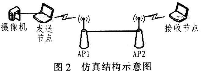
4 Application analysis Figure 2 is a schematic diagram of the video transmission system for example analysis. The video camera generates video files, which are transmitted to the receiving node through the sending node, and the wireless access points AP1 and AP2 in the middle; the sending node also has a CBR stream generator , Sent to the receiving node via intermediate nodes AP1 and AP2 as a background stream that affects video transmission. Set the CBR stream to use UDP protocol with a rate of 512 Kb / s. The bandwidth between AP1 and AP2 is 0.5 Kb / s. The link between the AP and the mobile node is IEEE802.11b with 1 Mb / s. Use the 100-frame image test sequence foreman_cif. Yuv, use MPEG4 codec to write simulation script file, run simulation in NS, and generate a trace file.

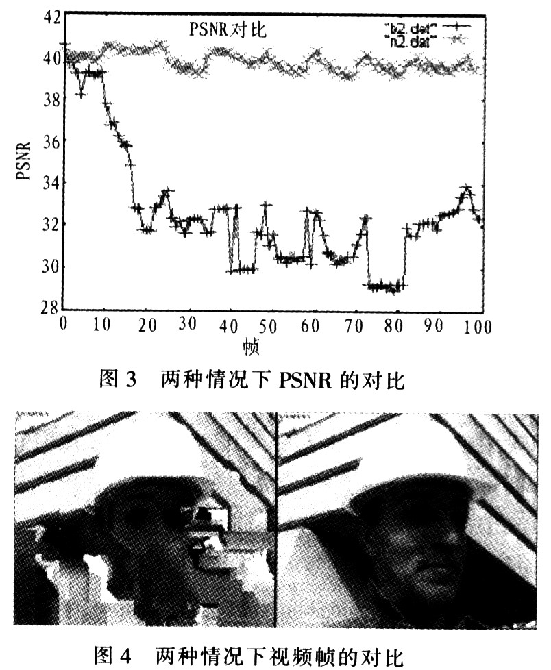
Use video compression files and trace files to write analysis programs, remove the packets lost due to packet loss from the video compression files, and obtain new compressed video files. After decoding, the video quality can be evaluated subjectively and objectively. In the wireless network, the transmission of the video stream is affected by the CBR stream, resulting in packet loss and distortion of the video image, b2 in Figure 3. dat and n2. The dat separately shows the PSNR of the video sequence in the presence or absence of the CBR background stream, indicating that the presence of the CBR stream deteriorates the video quality sharply.

Figure 4 compares the quality of the 74th frame video in two cases from a subjective point of view. The right frame is the case without the CBR background stream. The image quality is basically normal. The mosaic on the left frame indicates that the image is distorted.
5 Conclusion This paper selects NS-2 network simulator as the simulation environment to design and implement a test platform for wireless video QoS analysis. The requirements of the video QoS analysis for the test platform are proposed, after analyzing all the implementation processes. Demonstrate through examples. For simulation experiments that require the addition of a new video transmission protocol module in NS, the experimental platform can be applied to analyze and verify the effectiveness of the protocol. The experiment proves that the proposed scheme is completely feasible. According to the result, the video file can intuitively evaluate the network performance and reflect the running status of the actual network conveniently, which can greatly enhance the reliability of the simulation results, and is of great significance for the design and research of complex network topologies and related protocols.
Intelligent LV switchgear cabinet combines the intelligent power distribution monitoring terminal with the Internet of Things to realize data acquisition and intelligent connection, wherein the intelligent power distribution monitoring terminal monitors the status of power distribution equipment as well as the voltage, current, power and energy of the power distribution loop in real time, realizes the local monitoring of operating status via the HMI interface, so as to realize the local and remote comprehensive management of the LV power distribution system.
Intelligent Lv Switchgear,Low Voltage Switchgear,Low Voltage Switchgear For Distribution,Low Voltage Switchgear Panel
Jiangsu Sfere Electric Co., Ltd , https://www.elecnova-global.com