Radio Frequency IndenTIficaTIon (Radio Frequency IndenTIficaTIon) is an automatic identification technology that uses non-contact two-way data communication by radio frequency to identify the target and obtain relevant data. Now RFID has penetrated into various fields of people's daily life and has become a common technology. Its applications include logistics, asset management, and personnel access control. The basic components of an RFID system include a reader and an electronic tag. The reader antenna and the electronic tag antenna are spatial physical interfaces for realizing communication between the reader and the electronic tag. The operating frequency is the most important performance parameter of the RFID system. The RFID frequency range in China's UHF band is 840-845 MHz and 920-925 MHz.
Microstrip antennas are widely used in wireless communication systems because of their thin profile, small size, and low cost. In order to meet the requirements of the reader antenna operating in the two frequency bands of 840-845 MHz and 920-925 MHz, if the microstrip antenna design is adopted directly, there is a disadvantage that the frequency band of the antenna is relatively narrow and cannot meet the requirements of the two frequency bands. A new design idea is to design a dual-band microstrip antenna with two bands covering 840-845 MHz and 920-925 MHz. The advantage of this is that it satisfies both the requirements of the dual frequency band and, to a certain extent, filters the interference between the two frequency bands and the noise entering the receiving system of the reader.
Here, the multi-resonance method is adopted, and the dual-band coverage is realized by the structural design of the microstrip antenna. Under this idea, a low-back-valve dual-band microstrip antenna is realized by the combination of an E-shaped antenna and an inverted-F antenna (IFA). The antenna resonance is at 850 MHz and 920 MHz, VSWR = 1.09, and the bandwidth (VSWRlt; 2) satisfies the band coverage requirements. The antenna is fabricated on a 2 mm thick FR4 substrate, which is not only small in size, but also easy to adjust and easy to manufacture.
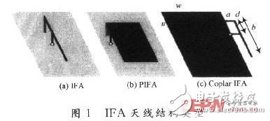
1.1 Introduction to inverted F antennaA typical inverted-F antenna (IFA) consists of a rectangular planar unit placed on the ground, a short-circuited surface parallel to ground or a shorting pin and a feed unit, as shown in Figure 1. IFA is essentially a dipole deformation. By bending the upper part of the dipole down to the ground, this reduces the height of the antenna, but the part parallel to the ground introduces capacitive reactance to the antenna. Therefore, it is necessary to introduce an inductive short-circuit surface or a shorting pin in the antenna structure to compensate for this part of the capacitance. The ground of the IFA antenna plays an important role because when the IFA patch has current, it will cause ground current excitation, and the final field is formed by the IFA patch current and its mirror current on the ground. This is how the IFA antenna works.

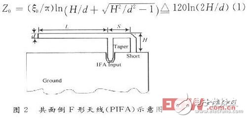
A coplanar inverted F-shaped antenna (PIFA) consisting of a terminal opening route of length L and a terminal short-circuiting line of length S is shown in Fig. 2. When the line width d of the transmission line is "H", the impedance Z0 of the transmission line can be expressed as:

In the formula (1): ξ = 120π is the wave impedance in the air. According to the transmission line theory, the input impedance is:

In the formula (2): β is a propagation constant. According to the formula (2), the reactances of the terminal open route of length L and the terminal short circuit of length S can be separately calculated, respectively:

When the loss is neglected, the input resistance of the antenna is the radiation resistance. According to the literature [8], there are:

When the length L=λ/4, the input reactance of the antenna can be obtained by equation (6), and the antenna is in a resonant state.

It can be seen from equation (7) that the input impedance of the antenna is pure resistance and is only related to the height H of the antenna. From the above derivation, it can be seen that for the adjustment of IPFA, the input impedance of the antenna can be adjusted by adjusting the length L to make it a pure resistance; then the input impedance of the antenna can be changed by adjusting the height H of the antenna to make it 50 The feeders of the Ω coaxial line are matched.
1.2 E-shaped antenna
The E-shaped antenna is formed by opening two parallel grooves on the basis of the ordinary microstrip patch unit. The position of the slot is symmetrical with the feed point. By adjusting the position, length and width of the slot, the bandwidth of the microstrip antenna can be effectively increased. According to the literature [8], a conventional microstrip patch antenna can be equivalent to a simple LC resonant circuit. The values ​​of L and C are determined by the length of current flowing through the surface of the conductor, while the E-shaped microstrip antenna is slotted. The antenna is changed from a single resonant LC loop to a dual resonant LC loop. The two resonant circuits are coupled together to achieve band broadening.
2 antenna design and simulationAccording to the above principle, a dual-frequency microstrip antenna is realized by combining an E-shaped antenna and an IFA antenna, as shown in FIG. According to the literature [9, 10], there are:

Where: W is the width of the antenna; c is the speed of light; f is the operating frequency; εr is the relative dielectric constant of the medium.

The length of the antenna is generally referred to λg/2, and λg is the wavelength in the medium.

The length of the resonant unit is:
![]()
In equation (10), the effective dielectric constant and ΔL can be calculated according to the following formula:

Where: εe is the effective dielectric constant; h is the thickness of the dielectric substrate.
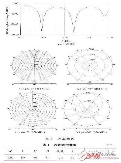
The dimensions W and L of the antenna can be estimated from the equations (8) to (12). Then, based on FDTD. Modeling on Ansoft HFSS 10.0, simulation optimization, and the antenna model shown in Figure 3 is obtained. The simulation results are shown in Figure 4. The structural parameters of the antenna are shown in Table 1.

As can be seen from Fig. 3, the microstrip antenna is composed of an E-shaped antenna and a coplanar IFA. The antenna is printed on an FR4 substrate having a thickness of 2 mm and a relative dielectric constant of 4.6. The antenna introduces an inductive shorting pin. To offset the capacitive. It is found that the performance of the antenna is particularly sensitive to the following parameters: the width of the slot has a greater influence on the second resonance point, and its influence is mainly reflected in the resonance depth without generating a frequency offset; the position of the short-circuit pin affects the first resonance point. It is relatively large, and its influence is mainly reflected in the resonance depth without generating frequency offset; the closer the distance between the grooves, the larger the resonance frequency, but the effect on the resonance depth is minimal.
As can be seen from Figure 4(a), the antenna resonates at 850 MHz, 920 MHz. The resonance point is VSWR=1.09, the bandwidth (VSWRlt; 2) is 840~860 MHz and 910~930 MHz, which fully meets the requirements of UHF China frequency band. It can be seen from the patterns of Figs. 4(b) to (e) that the back lobes of the antenna are relatively small at either 850 MHz or 920 MHz, thereby achieving a high front-to-back suppression ratio of the antenna.
3 ConclusionA novel dual-band microstrip antenna is designed for the UHF band RFID reader antenna compatible with the 840-845 MHz and 920-925 MHz dual-band requirements. Simulation and test results show that the antenna resonance is at two frequencies of 850 MHz and 920 MHz, and the bandwidth at two resonance points (VSWRlt; 2) meets the requirements of covering 840-845 MHz and 920-925 MHz dual-band, and has Lower back flap.
We provide quick-turn injection molding by many types of materials, like ABS, PA66, PBT, TPU, TPE, PVC, PE, NYLON 6, PC, silicone, TPE, EPDM, PUR, etc. Special for some plastic parts. Our advantages in internal prototyping, bridge tooling and short-run manufacturing, which can eliminate the costly and time-consuming for customers a lot.
ETOP experienced to support one-stop cable assembly solution service, including wire harness, palstic enclosure, silicone, metal, PCBA, etc.
Injection Molding Parts,Plastic Injection Molding,Low Cost Plastic Injection Molding,Plastic Mold Injection Molding
ETOP WIREHARNESS LIMITED , https://www.oemwireharness.com