With the rapid development of mobile technology and Internet technology, mobile networks will be the general trend of the development of next-generation networks. The wireless sensor network, one of the important subnets of the mobile network, can greatly expand the reach of the Internet. Due to the characteristics of low power consumption, low cost, distribution and limited resources of wireless sensor networks, the development of relevant protocols for wireless sensor networks has become one of the key technical factors for the development of wireless sensor networks. The traditional software development method is obviously not suitable for the development of wireless sensor protocol, and the new development model emerging recently is based on component-based software development method.
Component-based software development (CBSD, comp onent-based SOFTWARE development) method is a development method that can provide software reuse. Component is the basic unit for software development, reuse and software assembly. In component-oriented technology, an application software is not described by a large number of codes, but by a limited number of components, as shown in Figure 1 (a). Unlike traditional embedded software, componentized embedded software is composed of a set of software components, and one or several of these components are combined into a complete application; and new applications can also use existing components, thereby improving Software reusability. The embedded software developed under the traditional model provides dedicated services, and the software and the application are in one-to-one correspondence, as shown in Figure 1 (b). In the whole process, the amount of code is large, the complexity is high, the code reuse is small, and the update is difficult, and it does not meet the requirements of the wireless sensor node with limited resources.
TInyOS is a component-based wireless sensor network operating system. The system itself is a component library. Its development language nesC provides support for software component technology. By flexibly assembling the chip-level components of each fixed function, different hardware platform-level components can be easily constructed. Therefore, the method of developing componentized wireless sensor protocol under TInyOS system has been widely used. However, due to developers' over-reliance on existing integrated components, the performance of developed protocols is not ideal.
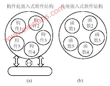
Figure 1 Componentized embedded software and traditional embedded software
1 Description of existing development methods
In order to simplify the development difficulty of the developer, the system packaged the bottom components of each chip into components. Call the most basic functional interface provided by the underlying hardware components to combine and implement some functional modules, such as preparing chip modules, sending data modules, receiving data modules, etc. The system's integrated operation of the hardware abstraction layer of each chip is basically the same. Figure 2 shows the relationship between the CC2420 system integration components and the hardware abstraction layer components.
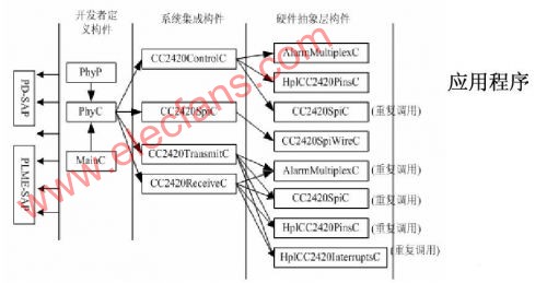
Figure 2 Relationship between system integration components and hardware abstraction layer components
As can be seen from Figure 2, the system integration components act as a bridge, which simplifies the development work for developers. However, when the system integration component calls the hardware abstract component to realize its own function, the problem of repeated invocation occurs. And the component CC2420SpiC is used in different layers (system integration layer and hardware abstraction layer), which itself makes the system integration layer and objects
The relationship between the abstract layer and the management layer becomes fuzzy and complicated, which makes it more difficult for developers to develop.
According to the programming of componentized systems, it can be known that the interface of the calling component needs to provide event events in the interface component. If multiple components reuse the same interface of the same component, each component that uses the interface needs to execute the event event in the interface once. When the system integration component calls the interface commands in the same hardware abstraction layer component at the same time, the signal event of the completed command will notify each component that uses the interface. This leads to a common problem of programming under componentized systems: fan-out. In order to solve this problem, the system had to change the nature of the component to generic type. And this will introduce a new component calling mode. All of these make the system integration components call the hardware abstraction layer components more complicated than actual, and the code execution efficiency is greatly reduced.
2 Directly call the description of the underlying component method
The research on the system integration component found that the application layer component finally calls the hardware abstraction layer component when calling the system integration component, but the system integration component reintegrates the hardware abstraction layer component into a large integration component to facilitate the user to find the interface. In fact, due to the characteristics of high integration of embedded software and hardware and limited hardware resources, in order to maximize the performance of software systems, embedded software developers are already very familiar with hardware before development. In this case, it is not necessary to add the system abstraction layer on top of the hardware abstraction layer. For developers, it is more intuitive and simple to directly call the underlying hardware abstraction layer components.
The specific implementation method is shown in Figure 3. In the operation of components, components that do not introduce new functions can cross the entire system integration component when wiring components, without affecting the system functions, and can simplify the development process and improve operation. effectiveness. Hereinafter, this method is simply referred to as the direct call method.

Figure 3 Simplified process of components
In Figure 3, component 1 and component 2 are not the components that provide the lowest level of functionality. They reintegrate the bottom component 3, component 4 and component 5, and finally use the functions of component 3, component 4 and component 5. Therefore, through the improved scheme, let the application component directly call component 3, component 4 and component 5, and let the functions of component 1 and component 2 be handed over to the application component to complete, which improves the execution efficiency and development efficiency of the code. In fact, combined with the componentized system, we can see that the simplified process in Figure 3 solves the fan-out problem. As long as the application component calls a hardware abstraction layer component, it can call the interface provided by the hardware abstraction component anywhere in the application component. Command. The wiring component also becomes simpler during wiring, without repeated wiring operations of multiple hardware abstraction layer components in the system integration component.
From the analysis of component-based systems and the underlying hardware abstract components and specific chips, it can be seen that system integration components all play the above role, and at the same time introduce new problems. If developers are familiar with hardware abstract components, they can use the components provided by the hardware abstraction layer directly across the system integration components. This simplifies the complex calling relationship between the system integration components in the original scheme, and more importantly, it can greatly improve the operating efficiency of the system. Taking the CC2420 system integration component as an example, its improved component calling scheme is shown in Figure 4. :
Figure 4 Relationship between components in the improvement plan
It can be seen from FIG. 4 that the components of the system integration level component layer in the original scheme are not called, but directly call the hardware abstraction layer components. From the comparison between Figure 4 and Figure 2, it is found that the original system integration layer component * can be moved to the PhyP component, which avoids the repeated use of the underlying component, and the entire structure is clearer and simpler. Therefore, the PhyP component needs to be improved so that it can complete the initialization of the RF chip and call the RF chip to send and receive data. Although it seems that the PhyP component is larger than the actual code, the test results of the improved system operation show that the work efficiency is increased by 10%, and the amount of code is reduced by 3000 lines.
3 Test direct call method
The design and implementation of IEEE802.15.4 will be applied directly. The IEEE802.15.4 standard has now become the de facto wireless sensor standard, and the protocol was developed on their respective hardware platforms. Taking the IEEE802.15.4 standard as an example, in the environment of TInyOS system and CC2420 radio frequency chip, we use the direct call method of this article to design and implement the standard, and test its working performance.
The design is carried out in accordance with the component programming ideas of TInyOS system. The physical layer will design two components (PhyP, PhyC), and related operations are performed through the two interfaces defined in the standard: data access interface (PD) and management interface (PLME). The component PhyP is the main realization component of the physical layer. It has three basic functions of initializing component, sending data and receiving data. The MAC layer designs two components: MacC and MacP, where MacP is the main execution component. There are two types of devices in the MAC layer: the coordinator node and the non-coordinator node. The coordinator node is responsible for establishing the network: establishing the network number (PANID), the short address of the node, and generating the beacon frame payload part. Non-coordinator nodes join the network established by the coordinator nodes to form a larger personal area network.
3.1 Functional test
The test program runs on two peer nodes and is tested in two stages. First, test the communication situation of the physical layer: No. 1 node generates a data packet with a payload of 0 to 9 and sends it to another No. 2 node. After receiving the above data packet, No. 2 node will keep the packet intact. The packet is sent back to the sender just now. The content of the data packet sent and received is the same, and the signal light flashes normally, indicating that the communication between the nodes is normal, and the physical layer design works normally. Further test the working condition of the MAC layer: set node 1 as the coordinator node and node 2 as the non-coordinator node. Node 1 initializes and establishes a PAN network. Node 2 requests to join the network created by node 1 to verify that the network is working properly. It can be known from the function test that the entire working process is in accordance with the provisions of the IEEE802.15.4 standard, and the functions of the standard are realized.
3.2 Efficiency test
In the work efficiency test, the application generates 50 data packets, and then calls the MAC layer sending interface to send the 50 data packets. The time starts when the application calls the MAC layer data interface, until the application layer receives the confirmation message that the packet is successfully sent. Record this response time, and increase the payload of the sent data packet in turn, from 10 bytes to 90, and record the response time of the payload and the increase. The efficiency test will be carried out in the original scheme and the protocol developed by the direct call method. The working parameters of the two different methods are counted. The final time distribution is shown in Figure 5.
Figure 5 Comparison of efficiency of sending and receiving data
As can be seen from Figure 5, in the case of 50 packets, when the payload of the packet is between 10 and 50 bytes, the response time difference between the two is not large, and the response time is increased by about 10%. When the payload is increased to When more than 50 bytes, the response time is increased by 30%, which is helpful to meet the real-time requirements of embedded systems
Conclusion
This solution analyzes the shortcomings of the existing development methods of wireless sensor networks, proposes a direct call method, and uses this method to achieve the IEEE802.15.4 standard, and finally achieves the expected goal. The scheme has high portability, good stability, small code amount, and is suitable for the characteristics of wireless sensor with limited resources and high real-time requirements. At the same time, the direct call method can be used to develop other communication protocols, such as: 802.11, LEACH, Bluetooth, etc.
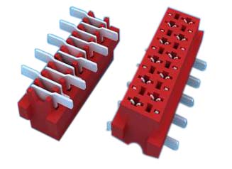
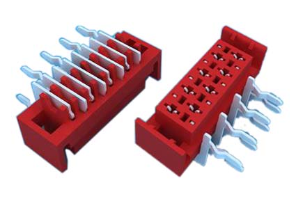
1.ANTENK Insulation Displacement termination connectors are designed to quickly and effectively terminate Flat Cable in a wide variety of applications. The IDC termination style has migrated and been implemented into a wide range of connector styles because of its reliability and ease of use. Click on the appropriate sub section below depending on connector or application of choice.
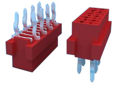
SPECIFICATION
Current Rating: 1.0Amp
Insulation Resistance: 1000MΩ min
Contact Resistance: 20mΩ max
Withstand Voltage: 500V AC/DC
Operating Temperature: -40°C to +105°C
Contact Material: Phosphor Bronze
Contact Plating: Au Over Ni
Insulator Material: High Temperature plastic UL94V-0
Ribbon Cable Connectors,Cable Connector,Cable Assembly,Connector Flat Ribbon Cable,Box Header Connector,Latch Header Connector,IDC Socket Connector,Dip Plug Connector
ShenZhen Antenk Electronics Co,Ltd , https://www.antenkcon.com