With the development of digital signal processing technology, more and more electronic products using digital audio technology. Digital audio interfaces have become the trend of development, and ECM and MEMS digital microphones using pulse density modulation (PDM) interfaces have also emerged. At present, ECM and MEMS digital microphones have become the mainstream of portable notebook pickup devices.
This article refers to the address: http://
Digital ECM or MEMS microphones have an irreplaceable advantage over traditional ECM microphones. First of all, mobile devices are becoming more and more digital, and digital pickup devices and technologies are urgently needed. Second, devices include more and more functional units, such as notebook computers, which integrate Bluetooth and WiFi wireless functions. The microphones are close to these interference sources. Equipment anti-interference requirements are getting higher and higher; third, the development of triple play requires Internet access, video and voice communication can be performed simultaneously, which usually encounters environmental noise and echo in mobile devices; fourth, from To improve production efficiency, I hope to use SMT soldering for the microphone. The digital microphone is suitable for SMT welding, which can solve the noise generated by various radio frequency interferences of the system. The digital array microphone pickup technology of Fudi Technology can suppress and eliminate the echo and environmental noise during the call, and the digital interface facilitates the connection with the digital system. .
Analog Microphone and Digital Microphone Microphone Structure: The ECM analog microphone is usually composed of a diaphragm, a back plate, a junction field effect transistor (JFET) and a shielded case. The diaphragm is a metal coated film. The back plate is made of an electret material and is charged with a high voltage polarization, and the two form a plate capacitor. When the sound causes the diaphragm to vibrate, the distance between the two changes, causing a change in voltage, completing the acoustic-electrical conversion. Using junction FETs for impedance transformation and amplification of signals, some high-sensitivity microphones use op amps to increase microphone sensitivity (see Figure 1a). The ECM digital microphone is usually composed of a diaphragm, a back plate, a digital microphone chip and a shielding case. The digital microphone chip is mainly composed of a buffer stage, an amplification stage, a low-pass filter, and an analog-to-digital conversion. The buffer stage completes the impedance transformation, the amplification stage amplifies the signal, the low-pass filter filters out the high frequency signal, prevents aliasing during analog-to-digital conversion, and the analog-to-digital conversion converts the amplified analog signal into a pulse density modulation (PDM) signal, which is usually used. Sampled 1-bit delta-sigma analog-to-digital conversion (see Figure 1b). MEMS analog microphones are mainly composed of MEMS sensors, charge pumps, buffer amplifiers, and shielded enclosures. Referring to FIG. 1c, the MEMS sensor is composed of a diaphragm made of a semiconductor process, a back plate and a bracket, and a suitable polarization bias is applied to the back plate by a charge pump. The buffer amplifier completes the impedance transformation and amplifies the signal. The MEMS digital microphone is mainly composed of a MEMS sensor, a charge pump, a digital microphone chip and a shielded casing, as shown in Figure 1d. In order to improve the anti-jamming capability of the microphone, a small filter capacitor is added between the internal power supply of the microphone and the ground, usually 10pF and 33pF in parallel.

Figure 1a ECM analog microphone
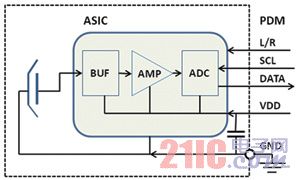
Figure 1b ECM digital microphone
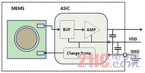
Figure 1c MEMS analog microphone
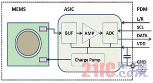
Figure 1d MEMS digital microphone
Microphone Bias Circuit: Compare the differences between ECM analog microphones, MEMS analog microphones and digital microphones through typical applications of microphone circuits in mobile phones. Figure 2a shows the bias circuit of an ECM analog microphone. In order to reduce interference, the microphone circuit in the mobile phone uses a differential output. After the microphone power supply is filtered by the R5 Resistor C9 capacitor, it is supplied to the FET inside the microphone through R6, and the differential output circuit is composed of R6 and R9. The output impedance of C15 and R6, R9 and the microphone form a low-pass filter to filter high-frequency signals beyond the voice band to prevent aliasing when the rear-stage circuit is replaced. C13 and C17 are isolated from DC bias, and R7 and R8 are used to prevent the discharge shock of the capacitor on the input end of the chip. The remaining 33pF capacitors are used to filter out RF interference. The analog input of the microphone output to the baseband chip uses differential routing to reduce noise and RF interference (see Figure 2b). Bias circuit for MEMS microphones. After the microphone power is filtered by the R1 resistor C2, it is supplied to the buffer amplifier and charge pump circuit built into the MEMS microphone. The sound signal picked up by the MEMS is converted into an analog electric signal, which is output after buffer amplification, filtered by a π-type filter composed of C5, R2, and C6, and the pseudo-differential circuit is wired to the baseband chip. Figure 2c is a bias circuit for a digital microphone. The microphone power supply is supplied to the microphone after simple filtering. The sound is converted into an analog electrical signal that is amplified by internal buffering. Under the driving of the clock signal (SCL), the final analog-to-digital conversion is converted into 1-bit PDM audio data, which is output from the data pin (DATA).
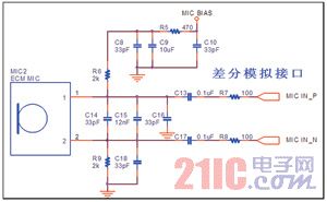
Figure 2a ECM analog microphone circuit
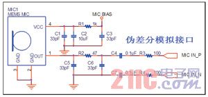
Figure 2b MEMS analog microphone circuit
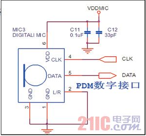
Figure 2c ECM/MEMES digital microphone circuit
Comparison of various types of microphones: Table 1 summarizes the performance indicators of ECM analog microphones, ECM digital microphones, MEMS analog microphones and MEMS digital microphones and their respective advantages and disadvantages.
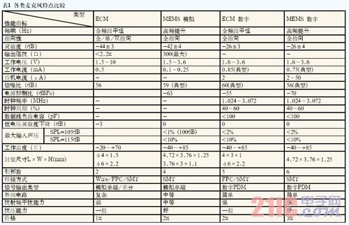
Pulse Density Modulation (PDM) signal and digital microphone interface:
The analog signal is converted to a PCM signal. According to the Nyquist criterion, the analog signal must typically be sampled with a fixed sampling frequency greater than 2 times. The analog to digital replacement, each sample point can be represented by multi-bit data. The more the number of bits, the higher the sampling accuracy and the smaller the distortion, but the circuit will be complicated and costly, which is not suitable for low-cost digital microphone applications. As shown in Figure 3b, the digital microphone usually uses a 1-bit delta-sigma analog-to-digital converter to oversample the analog signal (only for signals with limited bandwidth, not for wideband signals, such as video signals), and the sampling rate is external clock. provide. Oversampling can cause quantization noise away from the sampled audio signal. The closer to the main frequency fs of the signal, the smaller the noise amplitude. At the same time, the requirements against the aliasing filter are greatly reduced, and high precision can be achieved.
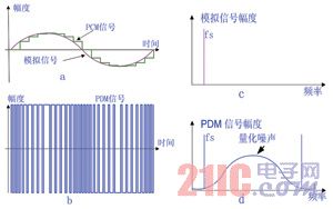
Figure 3 PDM signal
The digital microphone usually consists of five pins, power supply (VDD), ground (GND), clock (CLK), data (DAT) and channel selection (L/R). The digital microphone interface chip needs to provide microphone power (requires matching with system level) and external clock signal (1.024~3.074MHz). After the digital microphone acquires the clock signal, it goes from the power saving state to the normal working state. The pickup signal is oversampled and converted into a pulse density modulation (PDM) data stream (the more intense the signal amplitude changes, the denser the pulse density) is sent to the processing chip, and the internal Decimator is downsampled and low. Through filtering, the signal of the high frequency low bit stream is converted into the PCM signal of the low frequency high bit stream, and the quantization noise is filtered out at the same time. The PDM interface can be connected to two digital mics, share the clock and data lines, and select which channel's microphone is used when the clock is high and low through channel selection (L/R). Figure 4 shows the output signal of the digital microphone. When the clock is high, the microphone (MIC0) data line with L/R=0 remains in a high-impedance state, and the data of the microphone (MIC1) with L/R=1 is transmitted; when the clock is low, the microphone with L/R=1 (MIC1) The data line remains in a high-impedance state, and the data of the microphone (MIC0) with L/R=0 is transmitted.

Figure 4 Digital microphone output signal
Application of digital microphone array in mobile phone platform
The two digital microphones use the same set of power supplies, and the power supply voltage is the same as the voice processing chip FM34-395 (see Figure 5). The digital microphone array is configured as a main microphone (L/R ground) and a reference microphone (L/R power supply) through the L/R pin, and the picked up near-end signal is amplified by a digital microphone and converted into a PDM signal to be connected to the voice processing chip. FM34-395 chip. The two microphone signals are down-sampled and replaced into 16-bit PCM signals, and then subjected to correlation processing after amplification and filtering.
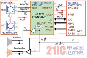
Figure 5 Typical application of digital microphone array on MTK mobile phone platform
In the handheld mode, according to the difference of the near-end signal picked up by the digital microphone array, steady-state and non-stationary noise suppression and linear echo cancellation processing are performed on the near-end speech, and the processed signal is sent to the baseband chip through the PCM pin (TxDp). The PCM IN pin is sent as an upstream signal and sent to the receiver (Receiver). The downstream signal is sent to the input pin (RxDc) of the FM34-395 through the baseband chip (PCM OUT pin), noise-suppressed, and based on the noise information provided by the digital microphone array to determine whether to activate the clear speech engine to brighten the receiver (Receiver) The sound makes the user still audible in the noisy environment, and serves as a reference signal for echo cancellation.
In the hands-free mode, according to the difference of the echo signals picked up by the microphone array, the near-end speech with the acoustic echo is cancelled, the processed speech is subjected to steady-state noise suppression processing, and the output signal is sent to the baseband chip through the PCM pin (TxDp). (PCM IN pin) as an upstream signal. The downstream signal is sent to the input pin (RxDc) of the FM34-395 through the baseband chip (PCM OUT pin), noise-suppressed, and based on the noise information provided by the digital microphone array to determine whether to activate the clear speech engine to brighten the receiver (Receiver) The sound makes the user still audible in the noisy environment, and serves as a reference signal for echo cancellation.
Positioning of the digital microphone array: The main microphone is placed under the front or bottom side of the mobile phone, which is as close as possible to the user's mouth. The reference microphone is placed on the upper or upper side of the back of the mobile phone, that is, close to the user's ear, so that in the handheld mode The signals picked up by the two microphones of the near-end speech digital microphone array are sufficiently different, and the far-distance noise is no difference. With the digital voice processor FM34-395, the directional fixed-distance pickup can be realized, and various environmental noises can be suppressed. .
Digital Microphone Arrays in Notebook Applications Figure 6 shows a typical application of a digital microphone array in a notebook computer. Usually, the digital microphone array and the camera module are installed in the center of the top of the notebook screen, so that when the user is in a video chat or a call, the sound source is located in the digital microphone array pickup beam, and can be transmitted out, and the noise on both sides is picked up. The sound beam is suppressed outside to achieve clear voice communication. The digital microphone in the array can be placed as a small digital microphone array at 10.5mm, or a wide array with a distance of 70-210mm. The corresponding software can be configured according to the microphone placement.
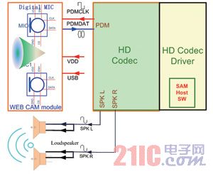
Figure 6 Typical application of a digital microphone array in a notebook computer
The digital microphone pick-up and convert to PDM format signal is connected to the digital audio interface of the notebook's HD Audio Codec sound card through a cable, down-sampled into two audio signals, and sent to the HD audio codec. The driver layer's small microphone array processing software (SAMSoft) handles Noise Suppression, Acoustic Echo Cancellation, Far Field Pick Up, and keyboard noise suppression.
Power Film Capacitors - Plastic Case
Polypropylene High Voltage Capacitor,Axial Film Capacitor,Axial Capacitor,SHV Capacitor
XIAN STATE ELECTRONICS TECHNOLOGY CORP. , https://www.shvcomponents.com