Introduction
With the rapid development of wireless local area network (WLAN) and global microwave access interoperability (Wimax), multi-frequency communication systems will become the leading development direction of wireless communication in the future. In this paper, a novel three-band pass filter design method is proposed. The resonant cavity of the filter is constructed by loading an inverted F-shaped branch in a common open-loop resonator by adjusting the length and position of the segments. The three resonant frequencies required can be achieved.
1. Design and analysis of traditional three-band pass filter
Conventional three-band pass filters usually use a stepped-impedance resonator (SIR). By adjusting the electrical length and characteristic impedance of the stepped impedance microstrip line, three resonant frequencies are achieved. This method is complicated in design and requires high impedance. The microstrip line can meet the design goal, which will make the high-resistance microstrip line in the design too thin, which will make processing difficult and affect the filter characteristics.
2. Design and analysis of novel inverted F-type branch loading open-loop resonator
2.1 Structure
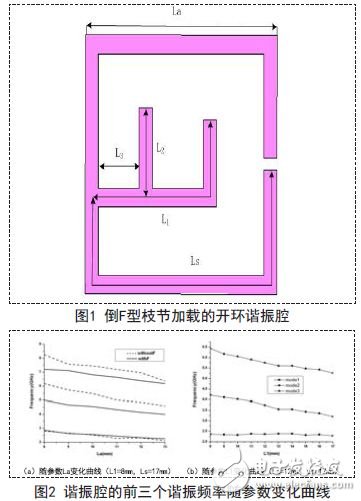
The structure is as shown in Fig. 1. After determining the basic resonance mode of the cavity by using the peripheral dimension La, it is only necessary to adjust the high-order resonance mode of the cavity to the required state by adjusting the lengths L1 and L2 of the branch and the positions Ls and L3. The position of the three-band pass filter is realized without changing the width of the microstrip line, thereby effectively avoiding the design using a too thin microstrip line, thereby making the processing of the three-band pass filter easier and effective. Small machining error.
2.2 Simulation
The simulation of the resonant cavity using software AnSOFt HFSS shows that the curves of the first three resonant frequencies with the structural parameters of the resonant cavity are given in Fig. 2. Fig. 2(a) depicts the curve of the first three resonant frequencies of the resonant cavity of the structure of Fig. 1 as a function of the outer dimension La of the cavity, and compares it with the resonant frequency of the open-loop resonator without the inverted F-shaped branch, using withF And withoutF said. It can be found from Fig. 2(a) that the fundamental mode resonant frequency of the resonant cavity is basically the same in both cases, and the frequency value of the high-order resonant mode changes significantly due to the existence of the inverted F-shaped branch. The F-shaped branch can effectively reduce the frequency value of the high-order resonance mode, and the frequency of the fundamental mode can be initially estimated by not loading the cavity of the inverted F-shaped branch, that is, changing the peripheral dimension of the cavity to adjust the resonant frequency of the fundamental mode.

The curve of the first three resonance frequencies of the open-loop resonator loaded with the inverted F-shaped branch as a function of the length L1 of the branch is given by Fig. 2(b). It can be seen from the figure that as the L1 increases, the frequency of the high-order mode decreases, and the frequency of the fundamental mode remains almost unchanged. Therefore, under the condition that the outer dimensions of the cavity are constant, we can change the high-order mode frequency by adjusting the value of the length L1 of the branch to achieve the required frequency ratio.
2.3 Influence of the position and length of the inverted F branch on the frequency ratio of the three-band pass filter
By changing the length parameters L1, L2 and the position parameters Ls and L3 of the branch, it is possible to calculate the ratio of the higher-order resonant mode frequency f3, f2, and the fundamental mode frequency f1, f3/f1 and f2 /f1, which vary with the parameter L1. The adjustable range of the frequency ratio of the method is relatively large. When Ls=7mm and 17mm, the parameters L1 and Ls have a greater influence on the frequency ratio, while at L3=1mm and 9mm, the influence of the parameters L3 and L2 on the frequency ratio is relatively small. Therefore, in the design, we can adjust the parameters L1 and Ls roughly to determine the required frequency ratio, and then change the values ​​of parameters L3 and L2 for more precise design to achieve our design goals.
It can be seen from the above analysis that changing the position and length of the inverted F branch can realize the design of the three-band pass filter with various frequency ratios, and the design method is simple in structure and easy to process, and can be widely applied to the multi-frequency wireless communication system. in.
3. Conclusion
In the design of multi-band pass filter, an inverted F-type branch-loaded resonant cavity that can realize three-way band design is proposed. Its characteristics are analyzed and studied. By adjusting the length and position of the branches, different The frequency ratio is adapted to the application of the multi-frequency communication system. The practicability of this method in designing a three-band pass filter for a wireless communication system is demonstrated.
10.1 Inch Laptop,win10 Laptops,win11 Laptops
Jingjiang Gisen Technology Co.,Ltd , https://www.gisentech.com