The servo is a position (angle) servo driver for those control systems that require changing angles and that can be maintained. At present, it has been widely used in high-end remote control toys, such as aircrafts, submarine models, and remote control robots. This article first introduced the composition and structure principle of the steering gear, followed by the introduction of the steering gear control and followability, and finally introduced the steering gear wiring method (three-wire wiring method) and installation.
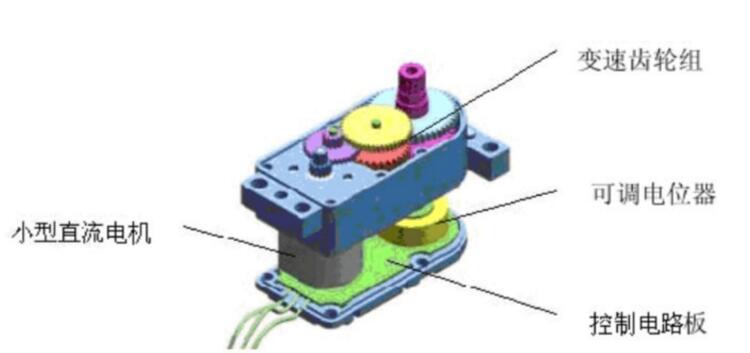
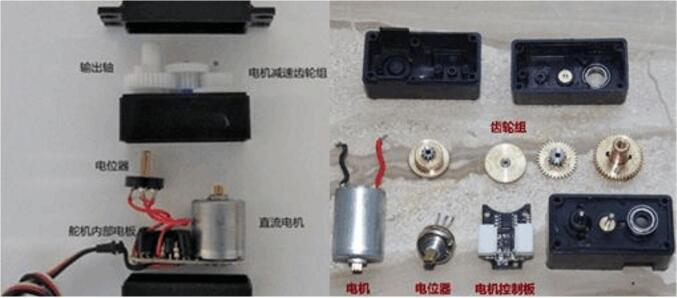
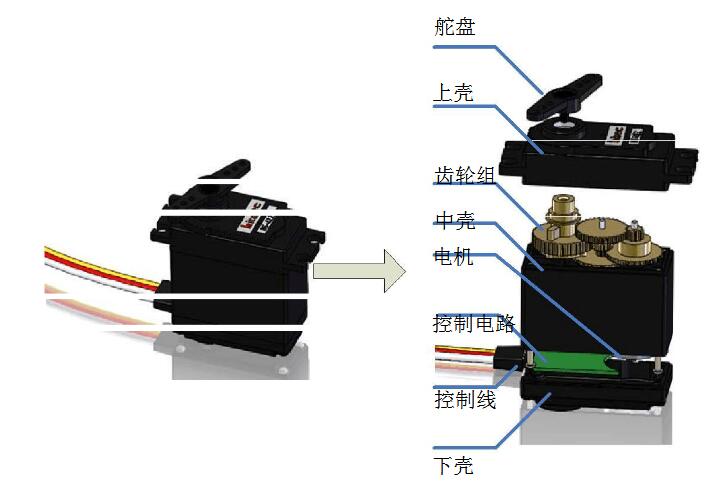
What constitutes a steering gear?In general, the servo mainly consists of the following parts: rudder plate, reduction gear set, position feedback potentiometer, DC motor, control circuit, etc., as shown in Figure 4 and Figure 5.
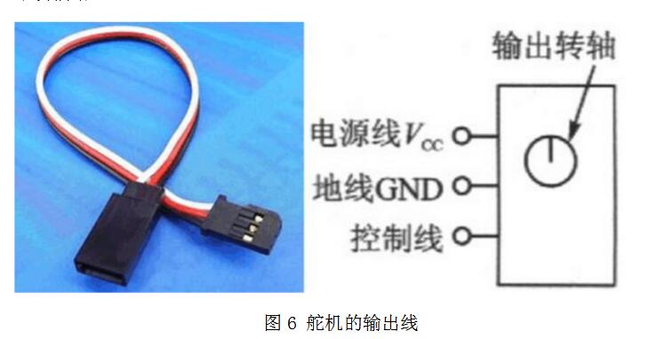
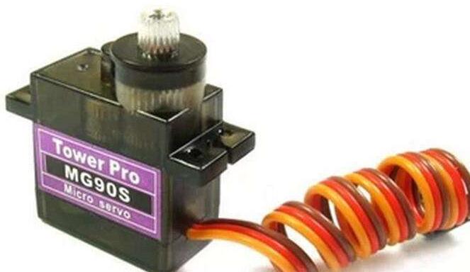
There are three input lines for the steering gear, as shown in Figure 6. In the middle of the red line, the power line, and the black line is the ground line. This root line provides the steering gear with the most basic energy guarantee, mainly the rotational consumption of the motor. There are two kinds of power supply specifications, one is 4.8V, one is 6.0V, corresponding to different torque standards, that is, different output torque, 6. OV corresponding to larger, specifically to see the application conditions; another line is the control signal The line, Futaba is generally white, JR is generally orange. In addition, it should be noted that some models of the SANWA's servo lead power lines are on the edge rather than in the middle and need to be identified. But keep in mind that red is the power source and black is the ground. It's generally not a mistake.
The servo is equipped with a potentiometer (or other angle sensor) to detect the rotation angle of the output shaft. The control board can accurately control and maintain the angle of the output shaft according to the information of the potentiometer. Such a DC motor control method is called closed-loop control, so the servo is more precisely a servo motor, English servo. Servo composition: rudder disk, reduction gear, position feedback potentiometer, DC motor, control circuit board and so on.
The control circuit board receives the control signal from the signal line to control the rotation of the motor. The motor drives a series of gear sets, and after deceleration, the drive is transmitted to the output rudder. The output shaft of the servo and the position feedback potentiometer are connected. When the rudder plate rotates, it drives the position feedback potentiometer. The potentiometer will output a voltage signal to the control circuit board for feedback, and then the control circuit board determines the motor according to the position. The direction and speed of rotation to achieve the target stop.
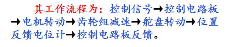
The workflow is: control signal → control circuit board → motor rotation → gear set deceleration → rudder rotation → position feedback potentiometer → control circuit board feedback.
The servo control generally needs a time base pulse of about 20ms. The high level part of the pulse is generally an angle control pulse part within the range of 0.5ms-2.5ms, and the total interval is 2ms. Take 180 degree angle servo as an example, then the corresponding control relationship is this:
0.5ms--------------0 degrees;
1.0ms------------45 degrees;
1.5ms------------90 degrees;
2.0ms-----------135 degrees;
2.5ms-----------180 degrees;
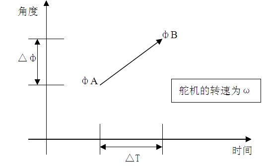
Follower Characteristics
Assume now that the servo is stable at point A. At this time, the CPU sends out a PWM signal and the servo rotates from point A to point B at full speed. In this process, it takes a while for the servo to move to point B.
Hold time Tw
When Tw ≥ △T, the servo can reach the target and there is time remaining;
When Tw ≤ △T, the servo cannot reach the target;
Theoretically: When Tw = â–³T, the system is the most consistent, and the servo moves fastest.
In the actual process, w is not the same, and the limit ΔT during continuous motion is difficult to calculate.
If our servo 1DIV = 8us, when the PWM signal changes in order of minimum change (1DIV = 8us), the servo has the highest resolution, but the speed will slow down.
Servo wiring method (three wire connection method)(1) Black line (ground line)
Red Line (Power Cord) Two Standards: 4.8V and 6V Blue/Yellow Line (Signal Line)
(2) Brown line (ground line)
Red Line (Power Line) Two Standards: 4.8V and Yellow Line (Signal Line)
The steering gear is a very important part of the remote control model radio control system. If you do not understand its performance, do not pay attention to the correct installation method, it will affect the flight attitude of the model, and if it is stuck, it cannot be manipulated, resulting in accidents. Therefore, before using the servo, it is necessary to understand its performance and installation method.
The model servos sold on the market in the past are mainly proportional ones, and the types include ordinary type, ultra-small type, powerful type, and special-purpose type. The following describes their respective performance.
normal type:
45 grams, 0.2 seconds/60 degrees, torque 3 kilograms centimeters. This kind of steering gear has relatively moderate performance in all aspects, and is generally used on models such as P3A-1, 2 and P2B-1, 2 which are not very large in size.
Ultra-small:
20 grams, 0.15 seconds/60 degrees, torque 2 kg.cm. Its small size, light weight, and low output torque are commonly used on models with small dimensions and relatively small rudder surface resistance, such as P5A, small electric models.
Strong type:
100 grams, 0.2 seconds/60 degrees, torque 9 kg.cm. This servo has a large output torque and can overcome the disadvantages of high resistance and large rudder surface. It is mainly used for models with large size and flying weight, high speed, and large rudder surface resistance, such as F3A, large-scale simulated aircraft model, modern aerobatic aircraft model, jet model aircraft, and F4 class model.
Special use type:
Most special-purpose servos have similar performance to the powerful type. It is usually used for special tasks, such as taking a rope (sailing), landing gear snakes and so on. In addition, some high-temperature and waterproof servos are mainly used in scientific research and industry. The general model is rarely used, but in recent years, the servo has developed rapidly in the field of civil models with the development of model products.
The circuits and gears inside the general steering gear are very delicate, and they are difficult to make. Many servos are used. The quality of Nissan's finished servos is good, and the remaining power is large, so it is not easy to hit teeth and is more durable. The quality of domestic servos is also good. The installation of steering gear is also very important, there are three main installation methods:
(1) Stick the servo directly to the model with glue. Requires high affixing technology and cannot be replaced. Usually used for some simple models.
(2) Fix the mounting holes on both sides of the servo well with screws. The advantage of this method is that it can be easily replaced.
(3) Fix it with matching fixing pieces and shock-absorbing pieces. For models with large-capacity internal combustion engines, this method is often used to reduce vibration damage to the steering gear.
The steering gear should be installed as close as possible to the center of gravity of the model. When conditions permit, servos and receivers should use power as much as possible. When the power supply voltage is insufficient, it should be replaced immediately to avoid the failure of the steering gear to cause air suspension. Different angles and force arm holes of the servo output disk (rocker arm) should be selected as large as possible to reduce the servo load. The output disk and the rudder surface can be connected with a special connecting rod or wire, the former is better
Finally, for the power motor control of some electric models, a steering gear was originally used as a switch, but the effect was not significant. Later, some people used a potentiometer directly to perform stepless operation on the motor. Now, some manufacturers have produced a continuously variable transmission of finished products (now called ESC), which is directly inserted into a channel, and performs stepless control such as acceleration and deceleration on the motor, which is both light and economical. However, in order to consider the use of vehicles and ship models, the transmission has a forward and reverse function, and only the forward function is allowed on the model aircraft. Therefore, when used on aeromodelling, it is advisable to ask a person to modify the circuit to prevent manipulation errors. The transmission is best to use a single set of power supply. If you use the power supply, it will affect the work of the receiver and the servo's action.
Silicon TVS / TSS:
Diode TVS (Transient Voltage Suppressor), also known as Transient suppression diodes, is widely used a new type of high efficient circuit protection device, it has a fast response time (the nanosecond) and high surge absorbing ability.When it ends of stand moments of high energy shock, TVS can bring the two ends at high rate from high impedance to a low impedance between impedance values, to absorb a large current moment, put it at both ends of the voltage restraint on a predetermined value, thus protecting the back of the circuit components are not affected by the impact of the transient high pressure spikes.
Silicon TVS Transient Voltage Suppresso,Silicon TSS Transient Voltage Suppresso
YANGZHOU POSITIONING TECH CO., LTD. , https://www.cnfudatech.com