Because of the wide variety of applications for ultra-wideband communications and radar, the design methods for UWB filters are also quite diverse. Many scholars have studied a variety of ultra-wideband filters with microstrip structures. Although the size of the microstrip filter is small and it is easy to integrate with other surface mount devices, its insertion loss is often very large. The insertion loss value is generally greater than 5dB. Another problem with microstrip filters is that their out-of-band suppression is often not very good. In this paper, we present a comb ultra-wideband filter design method with a passband of 2GHz to 4GHz and a stopband rejection of 11.23GHz.
2, filter design Figure 1 shows the structure of a 11-stage comb filter. The square waveguide has a width of a and a height of b, where there are 11 square columns, each having the same width w. The definition of the height of the column and the spacing of adjacent columns is shown in Figure 1. Inputs and outputs use SMA connectors. The diameter and height of small discs terminated in SMA inner conductors are defined as  with
with  .
.
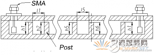
Figure 1 Comb filter structure
Using the design formula of the wide-band comb filter given in Chapter 8 of [7], the initial design parameters of the filter can be obtained. In this design, we use 11-level and 0.1-dB ripple design specifications. The "initial value" column in Table 1 shows the calculation result of each parameter.
Using the CST simulation software, the simulation of initial values ​​of the structure can be simulated in Figure 2. We can see that the passband's high-end edge frequency is lower than the design, and the return loss is not good. This is due to the fact that this filter has a relative bandwidth of 67%, which is a bit wider for our calculation formulae.
Table 1 The initial calculation value and the final optimization value of each parameter of UWB filter
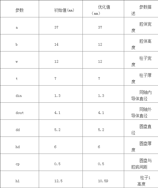
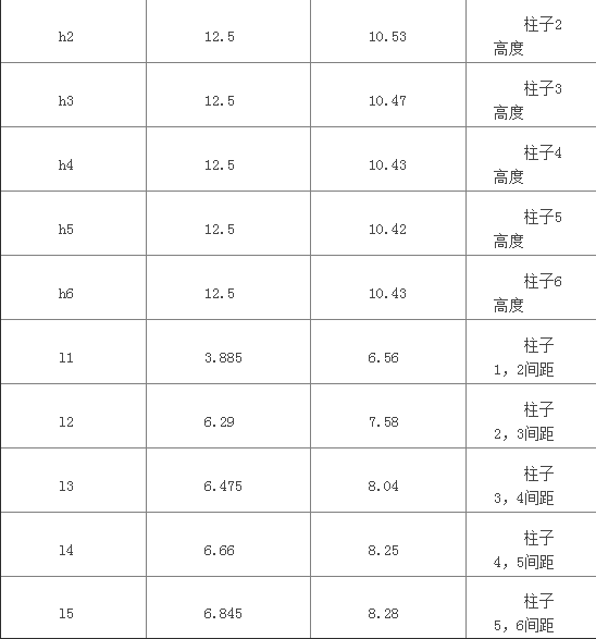

Figure 2 Simulation results substituting initial values
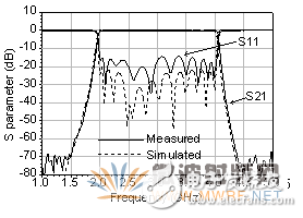
Figure 3 Optimized Filter Simulation and Test Results
After obtaining the above initial results, we use the optimization function of CST and we can obtain the final parameter value through optimization. The "optimized value" column of Table 1 gives the final value of each parameter. The simulation results are shown by dotted lines in FIG.
3, test resultsFigure 4 shows a sample of a comb filter machined according to the optimized values ​​in Table 1. Its size is 198mm X 51mm X 16mm. For comparison with simulation results, Figure 3 also shows the test curve of the sample. We can see that in the test results, except that the return loss is slightly higher than the simulation result, the other results are in good agreement with the simulation results. The test results show that the insertion loss in the 2GHz to 4GHz band is less than 0.35dB and the return loss is less than -15dB. In order to show the stopband rejection characteristic, Figure 5 shows the test curve from 1GHz to 15GHz. It can be seen that the parasitic passband is not generated until 11.23GHz.
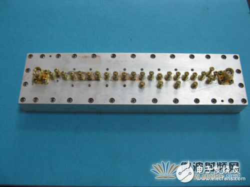
Figure 4 sample filter structure
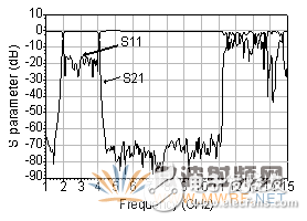
Figure 5 Sample filter parasitic parasitic pass test results
4 ConclusionThis article reports a waveguide ultra-wideband comb filter that has much lower in-band insertion loss and much better out-of-band rejection than a microstrip UWB filter. The test result of the sample filter shows that the 2GHz to 4GHz passband insertion loss is lower than 0.35dB, and the stopband suppression can reach 11.23GHz. This filter can be used in ultra-wideband communications and radar systems where insertion loss and out-of-band rejection requirements are very demanding. This technique can also be applied to systems that require effective suppression of higher harmonics.
The electrolyte material inside the electrolytic capacitor, which has charge storage, is divided into positive and negative polarity, similar to the battery, and cannot be connected backwards.A metal substrate having an oxide film attached to a positive electrode and a negative electrode connected to an electrolyte (solid and non-solid) through a metal plate.
Nonpolar (dual polarity) electrolytic capacitor adopts double oxide film structure, similar to the two polar electrolytic capacitor after two connected to the cathode, the two electrodes of two metal plates respectively (both with oxide film), two groups of oxide film as the electrolyte in the middle.Polar electrolytic capacitors usually play the role of power filter, decoupling (like u), signal coupling, time constant setting and dc isolation in power circuit, medium frequency and low frequency circuit.Non-polar electrolytic capacitors are usually used in audio frequency divider circuit, television S correction circuit and starting circuit of single-phase motor.
Electrolytic Capacitor,Aluminum Electrolytic Capacitor,High Voltage Electrolytic Capacitor,12V Electronic Components Capacitor
YANGZHOU POSITIONING TECH CO., LTD. , https://www.cnpositioning.com