For the communication system, the physical layer structure is one of the lowest-level designs. It is directly related to the duplex mode that we have already discussed in the low-cost chapter. It also determines the basic principles of resource allocation. Understanding the physical layer structure is the basis for understanding the technical details of the follow-up. It can be said that it is the boy-child skill of communication communication. We must lay the foundation. Otherwise, you will completely sleep after learning the channel!
First, a basic concept is explained: the physical layer structure consists of two parts, one is the frequency domain structure, and the other is the time domain structure (this is the source of the frame structure). Don't confuse it. The following Wu teacher will also follow the specific details. Frequency and domain time domain two points to see this idea, of course, in actual work, we say that the physical layer frame structure is basically equivalent to the physical layer structure, not so strict.
1 downlink physical layer structure
According to the system requirements of the NB, the downlink radio receiving bandwidth of the terminal is 180 kHz. Since the downlink uses 15KHZ subcarrier spacing, the downlink multi-access mode, frame structure, and physical resource unit design of the NB system use the original LTE design as much as possible.
In the frequency domain: NB occupies 180 kHz bandwidth (1 RB), 12 subcarriers, subcarrier spacing is 15 kHz, as shown in the following figure:

In the time domain: NB has a slot length of 0.5 ms, and there are 7 symbols in each slot, as shown in the following figure.

The NB basic scheduling unit is a subframe, each subframe is 1 ms (2 slots), each system frame contains 1024 subframes, and each superframe contains 1024 system frames (up to 3h). Here, unlike LTE, NB introduces the concept of superframes, which is the eDRX that was mentioned before when it comes to the characteristics of small power consumption (see NB-IOT Tai Chi chapter for small power consumption), in order to further save Electricity, the paging cycle is extended, and the terminal achieves the purpose of power saving by receiving less paging messages.

Is there a fainting of the wood above? In fact, it is not difficult, from the top down:
1 signal package for 1 symbol-"
7 symbol packages for 1 slot-"
2 slots are packed into 1 subframe -"
10 subframes combined into 1 radio frame ->
1024 radio frames make up one system frame (LTE is here) -
1024 system frames make up 1 superframe, over.
Calculated in this way, the total time of 1024 superframes = (1024 * 1024 * 10) / (3600 * 1000) = 2.9h.
Also understand the wood? So if you are a gangster, why not imagine the packaging of the above frame structure as a package for express delivery, a small box with a big box, a big box with a larger box? The reason is the same.
2 uplink physical layer structure
When I saw this, the following little classmates were already throwing rotten eggs. So easy!
However, after a quarter of a fragrant incense, you may fall into deep love for Teacher Wu as you watch the ascent.
In the frequency domain:
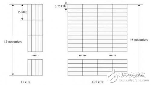
☟ occupies 180 kHz bandwidth (1 RB) and supports 2 seed carrier spacing:
â—¢15kHz: Up to 12 subcarriers can be supported: If it is 15KHZ, it can be washed and slept. Because the frame structure will be consistent with LTE, only the particles in the frequency domain scheduling will change from the original PRB to the subcarrier. This sub-frame structure is not elaborated.
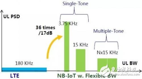
â—¢ 3.75kHz: Up to 48 subcarriers can be supported: If it is 3.75K, you first need to know where the benefit of designing 3.75K is. In general, there are two advantages. First, according to the "Blade of NB-IOT Strong Coverage", 3.75K will have a considerable power spectral density PSD gain compared to 15K, which will translate into coverage capability. Second, in the spectrum resource of only 180KHZ, the scheduling resources are extended from the original 12 subcarriers to 48 subcarriers, which can bring more flexible scheduling.
☟ Support two modes:
â—¢ Single Tone (1 user uses 1 carrier, low-speed IoT application, suitable for 15K and 3.75K subcarriers, especially suitable for low-speed applications of IOT terminals)
â—¢MulTI-Tone (1 user uses multiple carriers, high-speed IoT applications, only for 15K sub-carrier spacing. Pay special attention to the ability of the network to report terminal support if the terminal supports MulTI-Tone)
The relationship between the two modes and the two subcarrier spacings is as follows:
TIps:
It should be noted that whether it is Single Tone or MulTI-Tone transmission mode, NB is based on SC-FDMA multiple access technology in the uplink.
On the time domain:
☟Basic time domain resource units are Slots. Small students must pay attention to the concept of sub-frames for the uplink, but the concept of slot.
For the 15 kHz subcarrier spacing, the sound is still the same, 1 Slot = 0.5 ms, consistent with LTE, not to be discussed here.
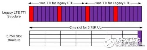
But for the 3.75kHz subcarrier spacing, 1 Slot = 2ms, this is quite different, as shown in the following figure:
This must be taken seriously when learning the NB frame structure.
Tips:
Here may be worth thinking about, is there any internal connection? Teacher Wu's understanding is that the subcarrier spacing of 3.75K in the frequency domain is 1/4 of 15K, while the time slot of 2ms in the time domain is exactly four times that of 0.5ms, which is actually equivalent.
The following figure is a schematic diagram of the structure of the uplink frame at 3.75KHZ, but this time we should look at the picture and turn it down. From the bottom up, please try to understand it yourself. Please note that it is 4 times in the time domain. .

3 uplink resource unit RU
For NB, there are two different subcarrier spacing forms for uplink, and the scheduling is also very different. In the uplink, NB-IoT separately defines the corresponding resource unit RU as the basic unit of resource allocation according to the number of Subcarriers. The basic scheduling resource unit is a RU (Resource Unit). The duration of the RU and the subcarriers in different scenarios are different. In particular, here, when understanding the RU, it should be noted that the scheduling unit after the combination of the resources in the time domain and the frequency domain is the RU.

As can be seen in the above table, NPUSCH is divided into Format 1 and Format according to the purpose. 2. Format 1 is mainly used to transmit ordinary data. Similar to the PUSCH channel in LTE, the Format 2 resource is mainly used to transmit UCI, similar to the PUCCH channel in LTE (one of the functions).
3.75KHz Subcarrier Spacing only supports single-frequency transmission, while 15KHz Subcarrier Spacing supports both single-frequency and multi-frequency transmission.

For Fomat1, the bandwidth of the 3.75KHz Subcarrier Spacing resource unit is a Subcarrier, the length of time is 16 Slots, that is, 32ms long, and the 15KHz Subcarrier Spacing single-frequency transmission, the bandwidth of one Subcarrier has 16 Slots. The length of time, which is 8ms. As can be seen from the above, in fact, the sum of the time-frequency resources occupied by the two single-frequency transmissions of Format 1 is the same. For the 15KHz Subcarrier Spacing multi-frequency transmission, there are three cases in total. In fact, the sum of the time-frequency resources finally occupied by these three cases is the same. In addition, the resource unit of 12 Subcarriers has a time length of 2 Slots, that is, 1 ms, and this resource unit is a Subframe in the LTE system.
For Fomat2, only single-frequency transmission is supported, and the sum of the resource unit of 3.75KHz Subcarrier Spacing and the time-frequency resource occupied by 15KHz Subcarrier Spacing resource unit is the same.
Here again, for the downlink, the sound of the waves is still the same, and the subframe is still used as the scheduling unit in the time domain.
4 Conclusion
This article mainly talks about the physical layer structure of NB. It will be the basis for understanding the details of NB technology. There are many details, and it is difficult to understand. It needs to be understood and laid the foundation for subsequent technical learning.

Knowing which specific Mac model you have is important.
Please contact with me, that I can tell you about your Mac model and generation will be displayed.
macbook 85w charger,apple macbook 85w charger,85w charger for macbook pro
Shenzhen Waweis Technology Co., Ltd. , https://www.huaweishiadapter.com