It is well known that semiconductor materials are greatly affected by ambient temperature during operation. High-power LEDs have lower photoelectric conversion efficiency, and only 10% to 25% of the electrical energy is converted into light energy during the work process, and the rest are almost converted into heat energy. In addition, the headlights of the car are installed in the hot engine compartment, and the heat generated by the high temperature water tank, engine and exhaust system places the LED headlights in a harsh environment. Conventional headlight bulbs generate much more heat than LEDs, but the brightness of the bulb output does not change due to heat. The focus of thermal design is on the uniform temperature design inside the housing. The light output of the LED will affect its own PN junction temperature stability due to its own heat or high temperature from the engine compartment. The important parameters such as LED luminous flux ФV and wavelength are directly affected by the PN junction temperature. This poor temperature cycle will cause luminescence. Efficiency and longevity have fallen dramatically. Therefore, heat dissipation has become an important issue in the design of LEDs as a light source.
This article refers to the address: http://
1. Cooling technology of car headlights
1.1 Passive cooling and active cooling
In the usual heat dissipation design, the circuit board on which the high-power LED is soldered is tightly fixed to the heat sink. The heat generated by the LEDs is conducted through conduction through the circuit board to the aluminum heat sink with better thermal conductivity. The fins of the aluminum heat sink are in contact with the air in a large area to dissipate the heat. In order to effectively reduce the thermal resistance between the heat sink and the circuit board, a heat conductive medium is filled therebetween. The selected radiator has a fin shape and area that can meet the design of the LED headlight cooling solution. This type of heat dissipation is called passive heat dissipation [2].
Active cooling is commonly used in liquid cooling, heat pipe, and air cooling. Since the liquid used for liquid cooling must be forced to take away the heat of the radiator under the driving of the pump, the heat pipe transfers heat by evaporation and condensation of the liquid in the fully enclosed vacuum tube by the heat transfer element with high thermal conductivity, neither of which Suitable for use in car lights. Air-cooled heat dissipation is most commonly used because of its low price and simple installation. For the case where the temperature in the central area of ​​the radiator is relatively concentrated due to the passive heat dissipation method, after the forced convection of the fan is added (see Fig. 1), the temperature unevenness of the radiator is obviously relieved.
1.2 LED heat dissipation channel design
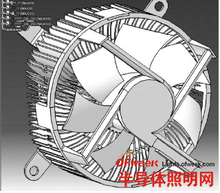
Figure 1: Forced convection after adding a fan
Usually, the LED is soldered on the printed circuit board (PCB) of the double-sided copper layer [1], and the bottom surface of the LED is soldered to the copper surface of the PCB. In order to improve the heat dissipation efficiency, a large copper layer is used as a heat dissipation surface. . This is the simplest heat dissipation structure [3].
The LED for automotive headlamps studied in this paper is a LEUMD1W4 [3] of OSRAM's current maximum power; the die heat dissipation design uses a LE3S package that is more conducive to heat dissipation [1]. The package is characterized by a large copper alloy thermal pad as the base and the die is fixed in the center of the base. At the same time, the insulating medium of the contact area between the LED base and the aluminum substrate is peeled off, so that the copper alloy base is in direct contact with the aluminum substrate. The heat on the pedestal is conducted directly to the outside of the LED. This internal structure removes the dielectric between the die and the pedestal to reduce thermal resistance and more directly derive the junction temperature of the die (see Figure 2a).
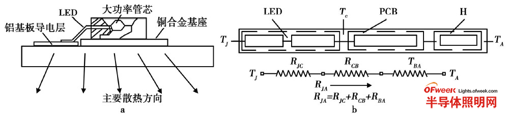
Figure 2: L ED, equivalent thermal resistance heat dissipation path for car headlights (click on image to enlarge)
The main heat dissipation path of LED automotive headlamps studied in this paper is: die→copper alloy substrate→aluminum substrate→heatsink or casing→ambient air (see Figure 2b). If the junction temperature of the LED is TJ, the temperature of the ambient air is TA, and the temperature at the bottom of the thermal pad is Tc (TJ>Tc>TA), the thermal conductivity of various materials is different during heat conduction, that is, there are different thermal resistances. The thermal resistance of the die conduction to the bottom surface of the thermal pad is RJC (thermal resistance of the LED), the thermal resistance of the thermal pad to the copper layer of the PCB surface layer is RCC, and the thermal resistance of the PCB to the ambient air is RBA, then the die is removed from the die. The junction temperature TJ is conducted to the total thermal resistance RJA of the air TA. The relationship between RJA and each thermal resistance is: RJA=RJC+RCB+RBA. The thermal conductivity of the copper alloy substrate and the aluminum substrate is close and the thermal resistance is small, and the thermal conductivity is good. That is, the better the heat dissipation performance [2]. The total thermal resistance of the heat dissipation structure is reduced by nearly 26% compared to conventional structures.
2. System design of the lamp environment
Since the output light flux of the LED at this stage is low, only the car low beam needs more than 1000 lm. Considering the light distribution requirements of the headlights of automobiles and the stability of electrical and optical parameters, LEDs used in automotive headlights often need to collect several or even dozens of LED components in a module to meet the requirements of the vehicle lights regulations. Requirements. Currently, we have a light distribution design for similar packages of O2star [1] and X2lamp products. The LEUMD1W4[3] single LED output light flux of OSTAR4chip headlights is greater than 350lm, and the array of 3 LEDs can meet the basic requirements of 1000lm.
(1) Increase the heat dissipation area to improve the conduction efficiency. In the LED car headlight low beam unit design, three high power LED arrays are on the aluminum substrate. The high concentration and heat dissipation of this closely-arranged high-power LED heat can be imagined. The test piece is practiced in that the aluminum substrate is closely attached to the heat sink. The two are filled with a cost-effective and easy-to-use thermal grease. In the entire cooling system, the silicone layer is the key to heat dissipation. At present, the thermal conductivity of the mainstream thermal grease is greater than 1W/m·K, and the high quality can reach 6W/m·K or more. The TG2244 thermal grease with a high thermal conductivity of 4. 4W/m·K is selected.
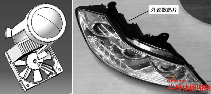
Figure 3: Air cooling and external cooling (click on image to enlarge)
(2) Forced convection to provide heat exchange with the outside air. Install a fan on the back of the heat sink to force forced air to flow. While the fan accelerates the heat exchange of the heat sink, the flowing air also carries away some of the heat directly from the PCB. Due to the narrowness and sealing of the lamp body, convection with the outside air is almost impossible. The forced convection of the fan in the air-cooled structure shown in Fig. 3a can alleviate the temperature unevenness of the central area of ​​the heat sink and the surrounding environment, so that the temperature inside the lamp body and the body of the lamp body are as close as possible. Helps to conduct internal heat through the outer casing and the external heat sink.
(3) The radiator part is external. According to the distribution in the engine compartment and the space of the lamp body installation, the lamp body heat sink is designed as two parts, internal and external, as shown in Fig. 3b. The external heat sink is designed on the upper edge of the lamp housing. The heat generated by the built-in LED is conducted by the built-in heat sink to the external heat sink, and then radiated by convection. Considering that the lights are usually turned on while driving, the engine compartment is subjected to strong convective air cooling and the temperature is relatively low. In addition, the upper edge of the lamp housing is exposed to the gap of the front cover of the vehicle. When the vehicle is running, the airflow introduced by the gap of the cover flows through the fins of the external heat sink, and the external heat sink is air-cooled by the air. The external heat sink plays a very good role in cooling the temperature inside the lamp.
3. Test methods and data
3.1 Test setup and equipment
According to the theoretical design and data simulation, the test model and LED headlamp working samples were produced. Sample preparation requirements are as close as possible to the target product, so that the research results can be converted into products faster and better. High-beam lights, low-beam lights, turn signals and position lights with LEDs as light sources are installed in the lamp body. The focus of the test observation is the effect of the internal temperature of the lamp body on the light decay.
The main test equipment is YF1000 optical color comprehensive analysis system, automatic light distribution test system for vehicle lights and multi-point temperature detector. The test points are: lamp illumination, light type, LED light source temperature, PCB temperature, heat sink temperature and temperature gradient at different positions of the lamp cavity [4]. The device has automatic recording and data preset functions to verify the relationship between heat dissipation and light decay.
3.2 Test data
Figure 4 is a graph showing the relationship between the temperature of the LED light source and the light decay in different heat dissipation modes. It can be seen that there are considerable differences in the three different heat dissipation designs of only PCB heat dissipation, passive heat dissipation with heat sink and active heat dissipation for forced convection. The latter two are capable of providing an emission rate of more than 80% at 105 °C.

Figure 4: Effect of different heat dissipation effects on light decay
In general heat calculations of power devices (such as power ICs), as long as the junction temperature is less than the maximum allowable junction temperature (typically 125 ° C). However, in the high-power LED heat dissipation design, the junction temperature TJ requirement is much lower than 125 °C. The reason is that TJ has a great influence on the light-emitting rate and life of the LED. The higher the TJ, the lower the light-emitting rate of the LED and the shorter the life. The junction temperature TJ of the high-power white LED given by OSTAR is related to the lifetime when the brightness is attenuated by 70%, as shown in Figure 5.

Figure 5: OSTAR LED junction temperature impact life diagram
We performed the light decay test under different conditions on the headlamp sample shown in Figure 3b. The test was based on the good heat dissipation of the LED. The module was installed in the closed lamp housing and the temperature detection point was near the LED light source. The ambient temperature at which the test data was collected was applied outside the lamp body. The test results show that the light decay is slow at an ambient temperature of 60 ° C; the light decay is exacerbated at 100 ° C (see Figure 6).
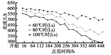
Figure 6: LED light decay in different temperature environments
4 Conclusion
The junction temperature generated by the PN junction of the LED itself increases, the light decay of the LED is intensified, the luminous efficiency is affected, and the lifetime is shortened. When LEDs are used as the headlight source for automobiles, multiple LED chip array designs are often used. Therefore, in the LED headlamp prototype design, firstly do the LED heat dissipation design to control the junction temperature, according to the operating environment of the LED headlights, control the driving power and temperature rise, the high power LED is less than 80% light decay and 3000h Life expectancy can be basically guaranteed. LED car headlight products have broad market prospects.
references:
[1] Wang Yaoming, Wang Demiao, Su Da. High-power LED heat dissipation package [J]. Journal of Southern Yangtze University: Natural Science Edition, 2009 (1): 58261.
[2] Wang Wei, Wang Wanliang, Pan Jiangen, et al. Research and analysis of high power LED reference thermal resistance test system [J]. LCD and display, 2009 (2): 2942298.
[3] OSTRALEUWD1W4DataSheet, OSRAMOptoSemiconductor, Rev. 03A2v[Z]. 2008.
[4] Lu Xiangyou, Hua Zezhen, Liu Meijing, and so on. Measurement and analysis of thermal characteristics of high-power LEDs based on heat pipe cooling [J]. Photoelectron. Laser, 2009 (1): 528.
[5] Wang Jing, Wu Fugen. Improve the key issues of high-power LED heat dissipation [J]. Electronic Design Engineering, 2009 (4): 1232125.
[6] Chen Yuan Deng. LED manufacturing technology and application [M]. Beijing: Publishing House of Electronics Industry, 2007.

Whaylan Portable solar photovoltaic panels use high quality single crystal solar cells with a high conversion rate of 23.5%, further achieving efficient conversion of solar energy to electricity without fear of power shortage. Equipped with high transmittance PET/ETFE membrane packaging, the latest generation of lamination technology and deep embossing process, light and convenient, and with waterproof, dustproof, high temperature resistance, self-cleaning functions, so as to further realize outdoor imagination, endless solar power.
Suzhou Whaylan new energy technology co., Ltd. is located in Suzhou Wuzhong Economic Development zone. It is a new energy conversion electric power equipment, energy storage transformation, energy management, on the basis of independent research and development, production, sales and after-sales service in the integration of high-tech enterprises, business scope covers from grid photovoltaic inverter, energy storage system, off-grid power generation systems and other fields.
3500W power station,Portable Rechargeable Generator 220v,Lighting Solar Energy,Solar Panel Power Station
suzhou whaylan new energy technology co., ltd , https://www.nbwhaylan.com