The D5026A is a driver IC designed by Shanghai Becker Electronics for energy-saving LED displays. Its design concept is energy-saving and compatible with existing solutions, which means it can be used for energy saving or compatibility with tradition. After calculation and testing, the display made with D5026A can save up to 30%. Here is a brief introduction to the energy saving principle of the D5026A.
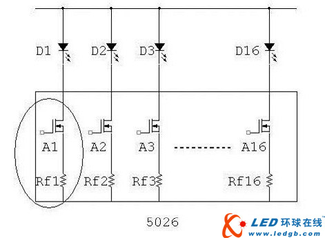
Figure 1 Traditional 5026 drive output structure
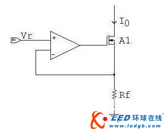
Figure 2 5026 constant current schematic of each unit
As we all know, the LED driver usually adopts the constant current source driving mode. Figure 1 is the traditional 5026 driving output structure, and Figure 2 is the constant current principle of each unit. Its constant current output current Io = Vr / Rf. In this output mode, the output voltage Vo is composed of a voltage drop Vr across Rf and a voltage drop Vds1 on the output transistor A1, that is, V.=Vr+Vds1. In the constant current state, Vds1 changes with load. When the output current is constant, we always have a point to make Io exit the constant current state when we reduce Vo. At this point we call it the lowest output voltage Vomin. We can combine Io=Vr/Rf with V.=Vr+Vds1. It is easy to see that the output will not be constant when V.-Vds1 is lower than Vr. At this time, Vds1 is about 0.1V, and the lowest output voltage is Vomin=Vr+0.1(V).
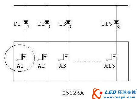
Figure 3 D5026A drive output structure diagram
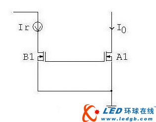
Figure 4 D5026A constant current schematic of each unit
Figure 3 shows the D5026A drive output structure, and Figure 4 shows the constant current principle of each cell. The D5026A uses the principle of a mirrored constant current source. Its output current Io is completely proportional to the area of ​​the two mirror tubes, ie Io=Ir x (Sa1/Sb1). Sa1/Sb1 is determined by the design of the IC layout, so the consistency can be very good.
Comparing Fig. 4 with Fig. 2, it is obvious that Vo=Vds at this time completely omits the voltage drop across the feedback resistor Rf. However, the voltage drop across the feedback resistor accounts for a large proportion of this. This is because if the feedback resistor voltage drop is set too low, it is difficult to compensate for the error caused by the feedback amplifier offset, and the consistency of the constant current source is difficult to guarantee. Usually the feedback resistor voltage drop is about 400mV-600mV. That is to say, the D5026A is 400mV-600mV lower than the traditional 5026 minimum output voltage Vomin under the same conditions.
Let's take the blue light as an example. Suppose the blue light's turn-on voltage is 3.2V. Under the factors of no line loss, the traditional 5026 minimum power supply voltage Vc=3.2+0.4(0.4-0.6)+0.1=3.7V (even To 3.9V). The D5026A can work at Vc=3.2+0.1=3.3V. Of course, the above considerations are ideal. If we consider factors such as line loss and power supply fluctuations, we recommend that the power supply voltage be 3.6V-3.8V.
We have calculated that if the existing 5V power supply display is changed to a 3.8V power supply display, it can save 24% directly without any changes in wiring, structure and control. In the past, these saved energy were applied to the 5026, resulting in a very high operating temperature of 5026, greatly reducing the reliability of the drive circuit. If the D5026A is used, the power consumption on the drive circuit will be greatly reduced, and the temperature rise will be extremely insignificant, that is, the power is saved and the reliability of the device is improved, and the heat dissipation consideration in the structural design is greatly reduced. Under the same conditions, the surface temperature of the 5026 with a 5V power supply is 73 degrees, and the surface temperature of the D5026A powered by 3.8V is only 39 degrees. Obviously, the advantages of using the D5026A are self-evident.
Edit: Nizi
Beginner Dry Herb Vaporizers,Hookah Dry Herb Vaporiser,Tobacco Dry Herb Vaporiser,Portable Dry Herb Vaporiser Pen
END GAME LABS , https://www.eglvape.com