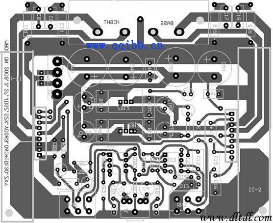
The circuit is a 10 × 12 (cm) board, you need to pay attention to the following points when doing:
Most of the component packages are made by themselves.
The line width of the front signal line I use is 40mil;
The power cord can be thickened and thickened after the wire is thickened;
The output line width of the power amplifier block should also be bold;
The line width of the ground wire should also be thickened to reduce the impedance of the component to ground;
Ordinary resistor-capacitor pads use 80mil solder holes 30mil;
Rectifier bridge pad 190mil solder hole 60mil;
Potentiometer pad 120mil soldering hole 60mil; do not reverse when doing package, the schematic diagram should be 1 pin grounded, 2 pin adjustable end.
Audio socket pad 120mil solder hole 50mil
TDA1521 is packaged in SIP9 with pad X=100mil, Y=80mil
NE5532 uses DIP8 package pad 90mil solder hole 32mil;
LM7812/LM7912 pad 85mil soldering hole 40mil
Other components modify the package according to the actual situation.
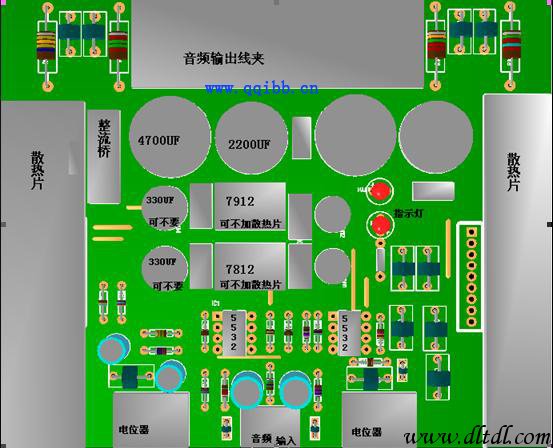
Wiring of jumpers: Because jumpers are often placed under large components for the sake of aesthetics when drawing PCB drawings, jumpers must be soldered before components are mounted. The jumper can be a single thick wire or a pin cut out from other components.
Welding of the resistor: Firstly, according to the assembly drawing, all the resistors are installed and soldered to the corresponding positions, and then the cut resistor pins are reserved for use as the next jumper.
Welding of the integrated block base: The two integrated blocks of the NE5532 are mounted on the base of the integrated block. Do not directly solder the integrated block to the circuit board, so the base must be soldered first. Note: 1 foot is facing to the upper left.
Electrolytic capacitors, 7812, 7912, LEDs: These components are also oriented, please pay special attention to the installation.
Special processing of the integrated block: 7812, 7912 heat is not large without heat sink, if you add heat sink, please note that the heat sink is not grounded. For example, the heat sink of the 7912 is connected to the input, and the heat sink of the TDA1521 is connected to the negative power supply. Once it is short-circuited with the board, the consequences are unimaginable. Therefore, when fixing the heat sink, it must pay attention to the insulation problem between the copper and the copper of the circuit board. Because of the large power consumption, the TDA1521 must add a larger heat sink (I chose a finned heat sink of 8cm × 5.5cm).
My 3D renderings
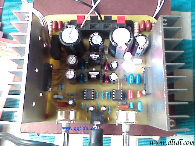
sample:
High Voltage Industrial High Bay Driver UFO
Fahold LTD -- Products Dept. has introduced a new series of 200-480V LED Round drivers, available in 100W,150W and 240W outputs.
Each model includes input voltage ranges from 200Vac to 480Vac. The FD-150GW constant current driver offers fixed and dimmable output models. Some models are Class 2 rated.
All models feature Metal housings and are IP65 rated--making them suitable for applications subject to moisture. They offer over-voltage, over-current and short circuit protection with automatic recovery to keep luminaires performing. it has the special heat dissipation design, wehich allow to work at Ta 65°C. The drivers are UL Recognized for both US and Canada, and are CE certified.

Industrial Lighting Led Driver,480V Constant Led Driver Circuit,UFO High Bay Lighting,Led Driver Power
ShenZhen Fahold Electronic Limited , https://www.fahold.net