IGBT is a switch, non-on-off, how to control his on or off, is based on the voltage of the gate source, when the gate source plus +12V (greater than 6V, generally take 12V to 15V) IGBT conduction, grid When the source is not applied with voltage or negative voltage is applied, the IGBT is turned off, and the negative voltage is added for reliable shutdown.
The IGBT does not have the function of amplifying the voltage. It can be regarded as a wire when it is turned on, and it is regarded as an open circuit when it is disconnected.
The IGBT has three terminals, G, D, and S. After the voltage is applied across G and S, the internal electrons are transferred (the characteristics of the semiconductor material, which is why the semiconductor material is used as a power electronic switch). The positive and negative ions are in one-to-one correspondence, and the semiconductor material is neutral. However, after the voltage is applied, the electrons accumulate to one side under the action of voltage, forming a conductive channel, because the electrons are electrically conductive and become conductors. . If the voltage applied across the GS is removed, the conductive channel disappears and it becomes electrically non-conductive and becomes an insulator.
IGBT working principle and function circuit analysisThe equivalent circuit of the IGBT is shown in Figure 1. As can be seen from Fig. 1, if a positive driving voltage is applied between the gate and the emitter of the IGBT, the MOSFET is turned on, so that the collector and the base of the PNP transistor are in a low-resistance state to make the transistor turn on; The voltage between the gate and the emitter is 0V, and the MOSFET is turned off, cutting off the supply of the base current of the PNP transistor, so that the transistor is turned off.
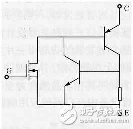
Figure 1 IGBT equivalent circuit
It can be seen that the safety and reliability of IGBTs are mainly determined by the following factors:
- the voltage between the gate and emitter of the IGBT;
- the voltage between the collector and the emitter of the IGBT;
- current flowing through the collector-emitter of the IGBT;
-- The junction temperature of the IGBT.
If the voltage between the gate and emitter of the IGBT, that is, the driving voltage is too low, the IGBT cannot work stably and normally, and if it exceeds the withstand voltage between the gate and the emitter, the IGBT may be permanently damaged; likewise, if The voltage allowed in the collector and emitter of the IGBT exceeds the withstand voltage between the collector and the emitter, and the current flowing through the collector-emitter of the IGBT exceeds the maximum current allowed by the collector-emitter, and the junction temperature of the IGBT exceeds its The IGBT can be permanently damaged by the allowable value of the junction temperature.
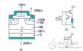
Insulated Gate Bipolar Transistor (IGBT)
The quality of the IGBT tube can be detected by the Rxlk block of the pointer multimeter, or by using the "diode" block of the digital multimeter to measure the forward voltage drop of the PN junction. Before the test, the three pins of the IGBT tube are short-circuited to avoid affecting the accuracy of the detection. Then, the two poles of the pointer multimeter are used to measure the resistance of the G and e poles and the G and c poles for the normal IGBT tube (normal). The positive and negative resistances between the two poles of GE and Gc are infinite; when the IGBT tube with damper diode is normal, there is a forward resistance of 4kΩ between the eC poles, the above measured values ​​are infinite; the last is the red with the pointer multimeter The pen is connected to the c pole, and the black pen is connected to the e pole. If the measured value is about 3.5kΩ, the measured tube is an IGBT tube with a damper diode. If the measured value is about 50kΩ, the measured IGBT tube does not contain a damper diode. For a digital multimeter, under normal conditions, the forward voltage drop between the eC poles of the IGBT tube is about 0.5V.
The schematic diagram of the IGBT tube detection with damper diode is shown in the figure. The connection of the test leads is infinite except for the connection shown in the figure.
If the resistance between the three pins of the IGBT tube is small, it indicates that the tube has broken through; if the resistance between the three pins of the IGBT tube is infinite, the tube is open circuit damaged. In actual work, IGBT tubes are mostly broken for breakdown.
The judgment of the quality of the power module is mainly the judgment of the freewheeling diode in the power module. For the IGBT module, we also need to judge whether it can be turned on and off in the presence of a trigger voltage. Inverter IGBT module detection: Turn the digital multimeter to the diode test file, test the forward and reverse diode characteristics between the IGBT module c1 e1, c2 e2 and between the gate G and e1, e2 to determine whether the IGBT module is intact.
Take the six-phase module as an example. Remove the wires of the U, V, and W phases on the load side, use the diode test file, connect the red meter pen to P (collector c1), and the black test pen sequentially measures U, V, W. The multimeter displays the value as the maximum; the test pen is reversed, black The meter is connected to P, the red meter is measured U, V, W, and the multimeter displays a value of about 400. Then connect the red test pen to N (emitter e2), the black test pen to measure U, V, W, the multimeter display value is about 400; the black test pen is connected to P, the red test pen is measured U, V, W, and the multimeter displays the maximum value. The forward and reverse characteristics of each phase should be the same. If the difference indicates that the performance of the IGBT module is deteriorated, it should be replaced.
When the IGBT module is damaged, only the breakdown short circuit occurs. The red and black test pens measure the forward and reverse characteristics between the gate G and the emitter E, respectively, and the values ​​measured by the multimeter are both maximum. At this time, it can be determined that the gate of the IGBT module is normal. If there is a numerical value, the gate performance deteriorates and the module should be replaced. When the forward and reverse test results are zero, it indicates that the detected one-phase gate has been broken through. When the gate is damaged, the voltage regulator of the protection circuit of the circuit board will also breakdown. The variable frequency speed control system is determined after the asynchronous motor is determined. Generally, the inverter should be selected according to the rated parameters of the asynchronous motor or according to the actual operating parameters of the motor. In practice, it has been found that the selection of the rated current of the inverter should be given a high degree of attention. If the inverter is selected only considering the capacity and does not consider the current, it will easily cause the inverter to burn out. Therefore, there must be sufficient room for calculating the inverter capacity.
Generally, the rated current of the inverter is required: ≥ (1.05 ~ 1.1) IN (1) or I change ≥ (1.05 ~ 1.1) IMAX (2)
I change----the rated current of the inverter
IN----rated current of the motor
IMAX----Maximum current in actual operation of the motor
When selected by capacity, the inverter capacity: P becomes ≥1.732&TImes; KINUN10-3 (KVA)(3)
In the middle
IN----Motor rated current
UN----Motor rated voltage
K----safety factor, generally selected (1.05~1.1)
For example, the rated voltage of the selected motor is UN=380V and the rated current is IN=7.2A.
According to formula (1), the rated current of the inverter is selected:
I change ≥1.1IN=1.1&TImes;7.2=7.92(A)
According to the formula (3) inverter capacity selection:
P change ≥ 1.732 & TImes; 1.05 & TImes; 7.2 × 380 × 10-3 = 4.98 (KVA)
According to the above calculation, the inverter can select the inverter with power ≥5KVA and rated current ≥8A.
The quality of the IGBT tube can be detected by the Rxlk block of the pointer multimeter, or by using the "diode" block of the digital multimeter to measure the forward voltage drop of the PN junction. Before the test, the three pins of the IGBT tube are short-circuited to avoid affecting the accuracy of the detection. Then, the two poles of the pointer multimeter are used to measure the resistance of the G and e poles and the G and c poles for the normal IGBT tube (normal). The positive and negative resistances between the two poles of GE and Gc are infinite; when the IGBT tube with damper diode is normal, there is a forward resistance of 4kΩ between the eC poles, the above measured values ​​are infinite; the last is the red with the pointer multimeter The pen is connected to the c pole, and the black pen is connected to the e pole. If the measured value is about 3.5kΩ, the measured tube is an IGBT tube with a damper diode. If the measured value is about 50kΩ, the measured IGBT tube does not contain a damper diode. For a digital multimeter, under normal conditions, the forward voltage drop between the eC poles of the IGBT tube is about 0.5V.
The schematic diagram of the IGBT tube detection with damper diode is shown in the figure. The connection of the test leads is infinite except for the connection shown in the figure.
If the resistance between the three pins of the IGBT tube is small, it indicates that the tube has broken through; if the resistance between the three pins of the IGBT tube is infinite, the tube is open circuit damaged. In actual work, IGBT tubes are mostly broken for breakdown.
The judgment of the quality of the power module is mainly the judgment of the freewheeling diode in the power module. For the IGBT module, we also need to judge whether it can be turned on and off in the presence of a trigger voltage. Inverter IGBT module detection: Turn the digital multimeter to the diode test file, test the forward and reverse diode characteristics between the IGBT module c1 e1, c2 e2 and between the gate G and e1, e2 to determine whether the IGBT module is intact.
Take the six-phase module as an example. Remove the wires of the U, V, and W phases on the load side, use the diode test file, connect the red meter pen to P (collector c1), and the black test pen sequentially measures U, V, W. The multimeter displays the value as the maximum; the test pen is reversed, black The meter is connected to P, the red meter is measured U, V, W, and the multimeter displays a value of about 400. Then connect the red test pen to N (emitter e2), the black test pen to measure U, V, W, the multimeter display value is about 400; the black test pen is connected to P, the red test pen is measured U, V, W, and the multimeter displays the maximum value. The forward and reverse characteristics of each phase should be the same. If the difference indicates that the performance of the IGBT module is deteriorated, it should be replaced.
When the IGBT module is damaged, only the breakdown short circuit occurs. The red and black test pens measure the forward and reverse characteristics between the gate G and the emitter E, respectively, and the values ​​measured by the multimeter are both maximum. At this time, it can be determined that the gate of the IGBT module is normal. If there is a numerical value, the gate performance deteriorates and the module should be replaced. When the forward and reverse test results are zero, it indicates that the detected one-phase gate has been broken through. When the gate is damaged, the voltage regulator of the protection circuit of the circuit board will also breakdown. The variable frequency speed control system is determined after the asynchronous motor is determined. Generally, the inverter should be selected according to the rated parameters of the asynchronous motor or according to the actual operating parameters of the motor. In practice, it has been found that the selection of the rated current of the inverter should be given a high degree of attention. If the inverter is selected only considering the capacity and does not consider the current, it will easily cause the inverter to burn out. Therefore, there must be sufficient room for calculating the inverter capacity.
Generally, the rated current of the inverter is required: ≥ (1.05 ~ 1.1) IN (1) or I change ≥ (1.05 ~ 1.1) IMAX (2)
I change----the rated current of the inverter
IN----rated current of the motor
IMAX----Maximum current in actual operation of the motor
When selected by capacity, the inverter capacity: P becomes ≥ 1.732 × KINUN10-3 (KVA) (3)
In the middle
IN----Motor rated current
UN----Motor rated voltage
K----safety factor, generally selected (1.05~1.1)
For example, the rated voltage of the selected motor is UN=380V and the rated current is IN=7.2A.
According to formula (1), the rated current of the inverter is selected:
I change ≥1.1IN=1.1×7.2=7.92(A)
According to the formula (3) inverter capacity selection:
P change ≥ 1.732 × 1.05 × 7.2 × 380 × 10-3 = 4.98 (KVA)
According to the above calculation, the inverter can select the inverter with power ≥5KVA and rated current ≥8A.
Lenovo Thinkpad parts,Lenovo Thinkpad replacement parts,Lenovo Thinkpad keyboard,Lenovo Thinkpad LCD
S-yuan Electronic Technology Limited , https://www.syuanelectronic.com