Firstly, the algorithm of UWB shaping pulse is introduced. Then, the shaping pulse of UWB is obtained based on Hermite matrix and Chirp signal. Based on the comparison and analysis of the performance parameters such as the bandwidth and center frequency of the Chirp pulse, several Chirp pulse signals are linearly superimposed. The simulation results show that the pulse signal generated not only satisfies the FCC's UWB pulse signal radiated power requirement. Moreover, the spectrum utilization of the pulse signal is also high, and it can effectively suppress interference to other narrowband systems.
UWB is a carrierless communication technology that uses nanosecond to sub-nanosecond non-sinusoidal narrow pulses to transmit data. It has a wide spectrum and is suitable for high-speed, close-range personal wireless communication. Pulse waveform design is a key factor in the performance of UWB systems. Traditional UWB signal carriers mainly include square wave pulse, Gaussian pulse, Hermite pulse and orthogonal ellipsoid wave function. With the development of surface acoustic wave devices (SAW), chirp signals can be generated and detected by pulse compression techniques using low-cost, low-power, low-complexity surface acoustic wave filters. Because Chirp pulse has good autocorrelation and matched filtering and sharp time domain characteristic signal, and its spectrum can meet the limits of U.S. Federal Communications Commission (FCC) for UWB radiation masking, it has high spectrum utilization. Increase the bandwidth appropriately to increase the transmission distance and transmission rate. This paper first introduces the influence of the performance parameters of Chirp pulse waveform on the pulse spectrum, and then linearly superimposes the Chirp pulse signal to obtain a wide-frequency short-time pulse signal, which can improve the spectrum utilization.
l UWB forming pulse calculationIn April 2002, the FCC revised the definition of “ultra-wideband†and adopted commercial licenses for ultra-wideband technology to limit power radiation. The spectrum range for ultra-wideband communications ranged from 3.1 to 10.6 GHz. The UWB pulse waveform is designed to meet the emission power spectral density requirements of indoor and outdoor UWB systems, and to maximize the spectrum utilization. Let the shaping pulse signal be ψ(t), which is equivalent to the system whose impulse response is h(t) and the frequency response is H(f), and then distribute the spectrum as much as possible within the FCC-defined spectrum limitation range. Define the pulse width of the shaped pulse signal to be Tm, then:

Its discrete expression is:

Where N is the number of sampling points for h(t) in time Tm.
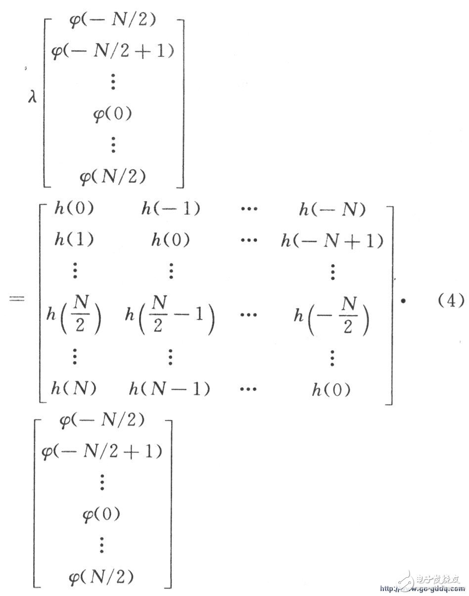
Expand the above formula to get the following matrix relationship:

It can be seen that the matrix H is a Hermite matrix, and the required shaping pulse ψ and attenuation factor λ can be obtained from the eigenvector and eigenvalue matrix of H. Since H is a Hermite matrix, the obtained eigenvector set is a linearly independent set of orthogonal vectors, and the eigenvalues ​​are real numbers, so the shaped pulses are not correlated.
Since the Chirp signal has the characteristics of large time bandwidth and low side lobes, in order to apply the Chirp signal as the basis function of the shaping pulse, it can be used as the impact response h(t) of the system, and the corresponding bandwidth is 3.1-10. At .6 GHz, its time domain expression is:

Where k=Ï€(fu-fl)/Tm, fu=10.6 GHz, fl=3.1 GHz, k is a linear modulation frequency, and its bandwidth B=kt, and then the shaping pulse of the UWB signal can be obtained according to the equation (5).
2 simulation resultsUsing the above theory, the Chirp signal is generated by equation (5), and then used as the impulse response of the system, and the Hermite matrix H of equation (4) is reconstructed, and the corresponding feature vector A is calculated therefrom to obtain the required shaping pulse. Let the number of pulse sampling points N=1 024 and the pulse duration Tm=10 ns. The simulation results of the shaping pulse are shown in Fig. 1 and Fig. 2. Fig. 1 is a time-domain and frequency-domain diagram when the bandwidth B is constantly changing at a fixed center frequency f0 = 6.85 GHz. It can be seen from Fig. 1(a) that as the waveform bandwidth increases, its time domain waveform becomes narrower and narrower; Figure 1(b) clearly shows the power spectral density of waveforms of different bandwidths.

Figure 2 is the same bandwidth, reflected in the time domain and frequency domain due to the variation of the center frequency of each Chirp pulse waveform.
It can be seen from Fig. 2(a) that as the center frequency changes to the high frequency portion, the period of change of the time domain waveform is shortened, which is reflected in the figure that the waveform is more and more dense. Its frequency domain power spectral density pattern changes as the center frequency changes.
In combination with the characteristics of the Chirp pulse described above, a plurality of Chirp pulse waveforms can be linearly superposed to produce a combined pulse that satisfies the FCC's limitation on ultra-wideband radiation masking and has a high spectral utilization.
3 Chirp combination pulseAccording to equations (2) and (5), the output function of the matched filter can be written as follows:

Broadband pulse signals can be obtained by superimposing several Chirp compression signals by the linear characteristics of the Fourier transform:

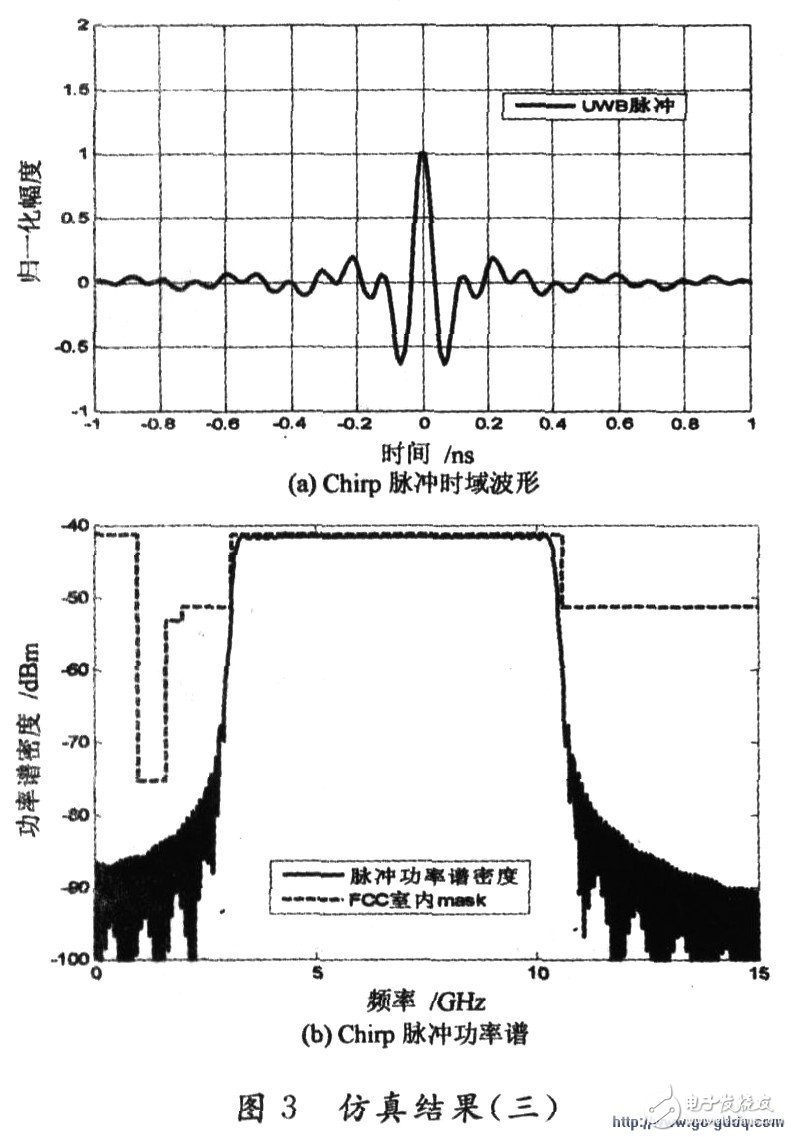
Figure 3 is a simulation result based on the above theory. Where N=42, B=300 MHz, Tm=10 ns.

It can be seen from Fig. 3 that the power spectral density of the Chirp combined pulse waveform satisfies the requirements of the FCC MASK, and its spectrum utilization is high. In the frequency band from 3.1 to 10.6 GHz, the power spectrum sidelobes of the waveform decrease rapidly, which can significantly reduce the out-of-band interference. If the interference between the UWB system and the existing narrowband system is considered, only the In the equation (7), the center frequency corresponding to the response frequency band is removed, so that the mutual interference can be achieved.
4 ConclusionIn this paper, we use the eigenvectors and Chirp pulses of Hermite matrix to discuss the method of UWB pulse waveform formation. By using the Chirp pulse waveform combined with the Hermite matrix, the power spectral density of the generated pulse waveform satisfies the FCC MASK specification, and has high spectrum utilization, which can reduce the interference to the existing narrowband wireless communication system. .
There are some draft products here, which will not be displayed on the website. These products can be modified later to enrich the content of the website. If you want to know more about our company, you can go to our website to check, there will be what you want, or you can consult us. Nice to meet you and looking forward to our cooperation.
Draft-waiting For Releasing,Draft-waiting For Releasing,Draft-waiting For Releasing
ETOP WIREHARNESS LIMITED , https://www.wireharness-assembling.com