Among various broadband fiber access network technologies, access network systems using SDH technology are the most commonly used. The birth of SDH solved the problem of the backbone network and user service demand due to the bandwidth limitation of the home media, which caused the problem of access bottleneck between the user and the core network, and increased the bandwidth of the transmission network. Utilization. Since the introduction of SDH technology in the 1990s, it has been a mature and standard technology. It is widely used in the backbone network, and the price is getting lower and lower. The application in the access network can make the SDH technology huge in the core network. Bandwidth advantages and technical advantages are brought into the access network field, making full use of SDH synchronous multiplexing, standardized optical interfaces, powerful network management capabilities, flexible network topology capabilities and high reliability, and benefiting from the development of access networks. Benefit. This article mainly explains the principle of sdh and warning maintenance.
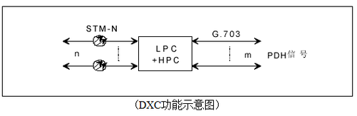
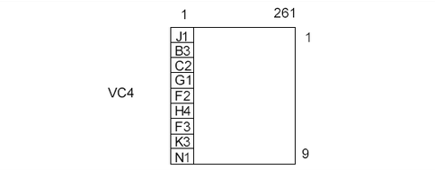
First, the logical function block of SDH equipmentThe SDH transmission network is composed of different types of network elements connected by optical cable lines. The transmission functions of the SDH network are completed by different network elements: uplink/down service, cross-connection service, and network fault self-healing. The network elements of the SDH transmission network mainly include: TM terminal multiplexer, ADM split/plug multiplexer, REG regenerative repeater, and DXC digital cross-connect equipment.
The TU-T uses a functional reference model to standardize SDH equipment. It decomposes the functions that the device should perform into various basic standard function blocks. The implementation of the function blocks is independent of the physical implementation of the devices. Different devices are flexibly combined by these basic function blocks to complete different functions of the device. The standardization of the device is standardized by the standardization of the basic function blocks, and the specification is also universal, and the description is clear and simple.
Below we use a typical functional block of a TM device to describe the role of each basic function block. Special attention should be paid to the alarm performance events and detection mechanisms monitored by each function block. As shown in Figure 1.
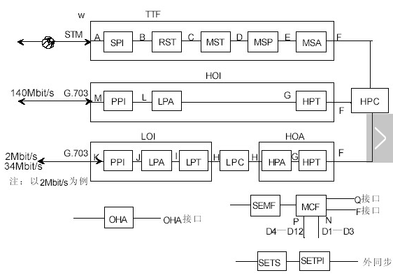
(Figure 1 logical function of SDH equipment)
In order to better understand the above figure, the function block names appearing in the figure are explained as follows:
SPI SDH physical interface TTF transfer terminal function
RST regeneration section terminal HOI high-order interface
MST multiplex section terminal LOI low-order interface
MSP multiplex section protection HOA high-order assembler
MSA multiplex section adapts HPC high-order channel connections
PPI PDH physical interface OHA overhead access function
LPA low-order channel adaptation SEMF synchronization device management function
LPT low-order channel terminal MCF message communication function
LPC low-order channel connects SETS synchronous device clock source
HPA high-end channel adaptation SETPI synchronization device timing physical interface
HPT high-end channel terminal
The figure above is a block diagram of the function block of the TM. The signal flow is that the STM-N signal on the line enters the device from the A reference point of the device, and then passes through A→ B→ C→ D→ E→ F→ G→ L→ M It is divided into 140Mbit/s PDH signals; it is split into 2Mbit/s or 34Mbit/s PDH signals after A→B→C→D→E→F→G→ H→ I→J→K. It is defined here as the direction of the device. The corresponding transmission direction is to multiplex the PDH signals of 140 Mbit/s and 2 Mbit/s and 34 Mbit/s into the STM-N signal frame on the line along the opposite direction of the two paths. These functions of the device are performed by each basic function block.
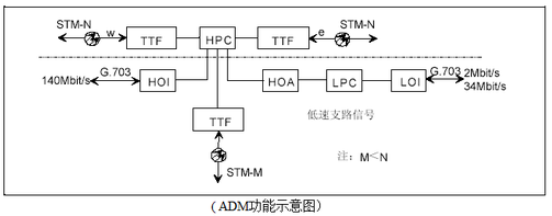
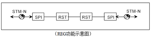
Common network elements of the SDH network are: TM (terminal multiplexer), ADM (drop add multiplexer), REG (regeneration repeater), DXC (digital cross-connect device). The following are the functional block components of various network elements. The functions of each network element can be understood through the composition of the function blocks.
The TM:TM terminal multiplexer is used at the terminal station of the network, and its function is to multiplex the low-speed signal of the tributary port into the high-speed signal STM-N of the line port, or to separate the low-speed branch from the signal of the STM-N. Road signal:
TM terminal multiplexer
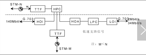
ADM: The role of ADM is to cross-multiplex the low-speed tributary signals into the east or west line; or split the low-speed tributary signals from the line signals received from the east or west line ports. In addition, the STM-N signals on the east/west line side can also be cross-connected:
ADM add/drop multiplexer
REG: The biggest feature of REG is that it does not up/down (divide/plug) circuit services, only amplifying or reproducing optical signals. The role of REG is to pass the optical signals on both sides of w/e via O/E, sampling, decision, regenerative shaping, and E/O on the e or w side:
REG regenerative repeater
DXC: Digital cross-connect device DXC is mainly a cross-connect function of STM-N signal. It is a multi-port device. It is actually equivalent to a cross matrix, which completes the cross-connection between signals. The core function of DXC is cross. Connected, powerful DXC can perform low-level crossover of high-speed signals in the cross matrix:
DXC digital cross-connect device
The main alarm maintenance signals generated by each function block of the SDH device and related overhead bytes are listed below.
. —SPI: LOS
. —RST: LOF( A1, A2), OOF( A1 , A2), RS-BBE( B1)
. —MST: MS-AIS (K2[b6 b8]), MS-RDI (K2[b6 b8]), MS-REI (M1), MS-BBE (B2) MS-EXC (B2)
. —MSA: AU-AIS (H1, H2, H3), AU-LOP (H1, H2)
. —HPT: HP-RDI (G1[b5]), HP-REI (G1[b1 b4]), HP-TIM (J1), HP-SLM (C2), HP-UNEQ (C2) HP-BBE (B3)
. —HPA: TU-AIS (V1, V2, V3), TU-LOP (V1, V2), TU-LOM (H4)
. —LPT: LP-RDI (V5[b8]), LP-REI (V5[b3]), LP-TIM(J2), LP-SLM(V5[b5 b7]), LP-UNEQ (V5[b5 b7] ), LP-BBE (V5[b1, b2])
A brief description of the mechanism for generating these alarm maintenance signals is as follows
The meaning of each alarm signal is specified in the ITU-T Recommendation:
. LOS signal loss
Input no optical power, optical power is too low, optical power is too high, making BER worse than 10-3
. OOF frame out of step
Search for A1 A2 byte time exceeds 625μs
. LOF frame loss
OOF lasts for more than 3ms
. RS-BBE regenerator section background error block B1 checksum error block of regenerative section STM-N
. MS-AIS multiplex section alarm indication signal
K2[6-8]=111 more than 3 frames
. MS-RDI multiplex section remote degradation indication
The peer detected that MS-AIS and MS-EXC were sent back by K2[6-8] (value is 110, which is different from AIS).
. MS-REI multiplex section remote error indication
The number of multiplex section error blocks detected by B2 is sent back by the peer through the M1 byte.
. MS-BBE multiplex section background error block detected by B2
. MS-EXC multiplex section error overdose detected by B2
. AU-AIS management unit alarm indication signal
The entire AU is all 1 including AU-PTR
. AU-LOP snap-in pointer is missing
Received invalid pointer or NDF for 8 consecutive frames
. HP-RDI high-order channel remote degradation indication
Received HP-TIM HP-SLM
. HP-REI high-order channel remote error indication
The number of error blocks detected by the receiving end B3 byte sent back to the originating end
. HP-BBE high-order channel background error block
Display the number of error blocks detected by the B3 byte on the local end.
. HP-TIM high-order channel trace byte mismatch
J1 receivables are inconsistent with actual receipts
. HP-SLM high-order channel signal mark mismatch
C2 receivables are inconsistent with actual receipts
. HP-UNEQ high-order channel is not loaded
C2=00H exceeds 5 frames
. TU-AIS tributary unit alarm indication signal, the entire TU is all 1 including TU pointer
. TU-LOP tributary unit pointer lost
Received invalid pointer or NDF for 8 consecutive frames
. TU-LOM tributary unit lost frame
H4 consecutive 2-10 frames are not equal to the multiframe order or invalid H4 values
. LP-RDI low-order channel remote degradation indication received TU-AIS or LP-SLM LP-TIM
. LP-REI low-order channel remote error indication is detected by V5[1~2]
. LP-TIM low-order channel trace byte mismatch is detected by J2
. LP-SLM low-order channel signal mark byte mismatch is detected by V5[5-7]
. LP-UNEQ low-order channel is not loaded with V5[5-7]=000 more than 5 frames
To streamline the inherent relationship of these alarm maintenance signals, we have listed two alarm flow diagrams below. Figure 2 is a concise flow chart for generating TU-AIS alarms. TU-AIS is often encountered when maintaining equipment. Through the analysis in Figure 2, it is convenient to locate the fault points and causes of TU-AIS and other related alarms.
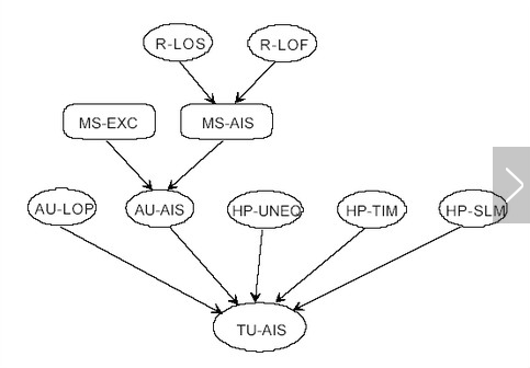
(Figure 2 is a simplified flow chart of TU-AIS alarm generation)
Figure 3 is a more detailed alarm flow chart of each functional block of the SDH equipment. It can be seen that the relationship between the alarm maintenance signals generated by each functional block of the SDH equipment.
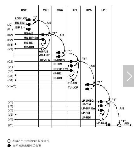
(Figure 3 SDH function block alarm flow chart)
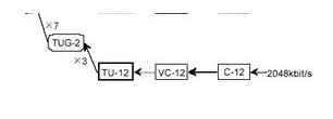
Third, the PDH is multiplexed into SDH STM-N signal stepsThe ITU-T specifies a complete set of multiplexing structures, that is, the multiplexing route through which the three series of digital signals of the PDH can be multiplexed into STM-N signals in various ways. The multiplexing route specified by ITU-T is shown below.
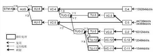
(G.709 Multiplexing Mapping Structure)
PDH bandwidth:
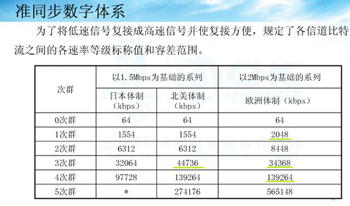
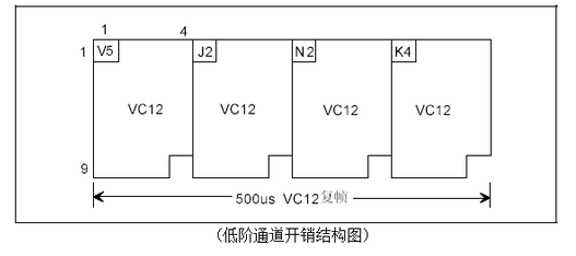
Although there are many routes for multiplexing a signal into SDH STM-N signals, for a country or region, the multiplexing route must be unique. The optical synchronous transmission network technology system in China specifies a 2 Mbit/s signal. The basic PDH series is used as the payload of SDH, and the multiplexing route of AU-4 is selected. The structure is shown in Figure 4.
(Figure 4 China's SDH basic multiplexing mapping structure)
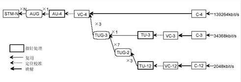
Fourth, SDH frame structure and segment overheadSDH uses a rectangular block-like frame structure based on a byte structure. STM-N is a code block consisting of 9 rows and 270×N columns of bytes, as shown in FIG. Each frame has a total of 9 × 270 × N bytes, each byte is 8 bits. For STM-1, the frame capacity = 270 × 9 = 2430 (bytes); the number of bits of one frame = 270 × 9 × 8 = 19440 (bit); the length of time (frame period) of one frame is 125 μs, That is, 8000 frames per second are transmitted, and the information transmission rate is 9×270×8×8000=155.520 (Mbi/s). The higher level STM-N signal consists of N times the basic module STM-1 signal.
(Figure 5 STM-N frame structure diagram)
The frame structure can be divided into three basic areas: Segmentation Overhead (SOH), Information Payload (Payload), and Administrator Unit Pointer (AU-PTR).
(1) Segment overhead (SOH) refers to the bytes that must be attached in the STM frame structure to ensure normal information payload and flexible transmission. These bytes are mainly used for network operation, management, and maintenance. Segment overhead can be divided into regenerator section overhead (RSOH) and multiplex section overhead (MSOH).
(2) Information payload area (Payload) refers to the place where the information symbols from various low-speed branches are stored in the frame structure. These information symbols are encapsulated in different containers and reach the rate of STM-1.
(3) Management unit pointer. It is used to identify the location of the first byte of the information payload in the entire management unit (that is, to indicate the location of VC-4 in AU-4) in order to properly separate the payload at the receiving end. (Huawei's "SDH Overhead and Pointer" is more clear http://)
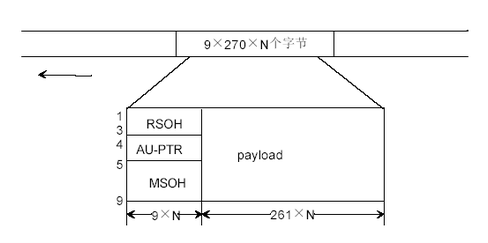
Five, channel overhead(1) High-order path overhead HP-POH
J1 channel trace byte
The AU-PTR pointer refers to the specific position of the starting point of VC4 in AU-4, that is, the position of the first byte of VC4, so that the receiving end can correctly correct the value of AU-PTR in AU-4. Isolation of VC4. J1 is the starting point of VC4. The AU-PTR points to the position of the J1 byte. The function of this byte is similar to the J0 byte. It is used to repeatedly send the high-order channel access point identifier to make the channel. The receiving end can confirm that it is in continuous connection with the specified transmitting end, and the request also matches the J1 bytes at both ends of the transmitting and receiving.
Channel BIP-8 code B3 byte
Channel BIP-8 code B3 byte is responsible for monitoring the error performance of VC4 transmission in STM-N frame. The monitoring mechanism is similar to B1 and B2, except that B3 performs BIP-8 check on VC4 frame. If the error block is detected at the receiving end, the performance monitoring event HP-BBE high-order channel background error block of the device displays the corresponding number of error blocks, and the performance monitoring event HP-REI of the corresponding VC4 channel at the originating end G1 byte b1~b4 backhaul), high-order channel remote error block indication, showing the number of error blocks received at the receiving end.
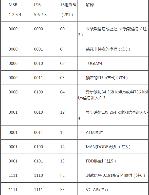
C2 signal tag byte
C2 is used to indicate the multiplex structure of the VC frame and the nature of the information payload, such as whether the channel is loaded, the type of service carried, and how they are mapped. For example, C2=00H means that the VC4 channel is not loaded with signals. At this time, the full "1" code TU-AIS is inserted into the payload of the VC4 channel, and the device has a high-order channel unloaded alarm HP-UNEQ; C2=02H indicates VC4. The loaded payload is multiplexed according to the multiplexing path of the TUG structure; C2=15H indicates that the load of VC4 is the signal of the FDDI fiber distributed data interface format.
☆Technical details
The J1 and C2 byte settings must be consistent between the receiving and transmitting ends. Otherwise, the HP-TIM high-order channel tracking byte mismatch will occur on the receiving device, and the HP-SLM high-order channel signal tag byte mismatch. Both of these alarms cause the device to insert a "1" code TU-AIS alarm indication signal to the lower structure TUG3 of the VC4.
C2 byte encoding
G1 channel status byte
G1 is used to return channel termination status and performance to the VC4 channel source device, allowing monitoring of the status and performance of the entire bidirectional channel at either end of the channel or at any point in the channel. The number of error blocks of the VC4 channel detected by the B3 detected by the B1~b4 of the G1 byte is also HP-REI; when the receiving end receives the AIS, the error is over-limit, and the J1 and C2 are mismatched by the G1 byte. The 5th bit sends back an HP-RDI high-order channel remote degradation indication, so that the originating end knows that the receiving end receives the status of the corresponding VC4, so as to find the positioning fault in time. B6 to b8 of the G1 byte are temporarily unused.
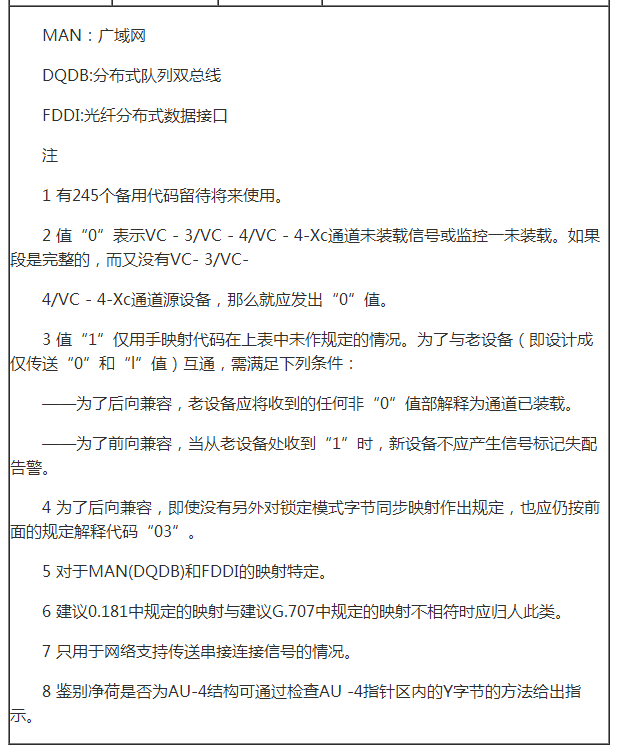
(2) Low-order path overhead LP-POH
In order to facilitate the adaptation of the rate, the concept of multiframe is adopted to form four multiframes of C12 base frames. The four base frames in a multiframe are actually the same 2M channel as the signal. Low-order path overhead refers to the channel overhead in VC12. Of course, it monitors the transmission performance of VC12 channel level. The figure above shows a multi-frame structure of VC12. The low-order POH is located at the first of each VC12 base frame. Bytes. A set of low-order path overhead has a total of 4 bytes V5, J2, N2, K4. In other words, it takes four frames to complete all the channel overhead. These four frames are frames of a VC12 channel.
Sixth, BIP-8 error detection principleBit Interleave Parity 8 Bit Code BIP-8 B1 This byte is used to regenerate the B1 of the segment error detection and is located in the regenerator section overhead.
The BIP-8 parity is as follows:

If a signal frame has 4 bytes (just one hypothesis, the actual frame has many bytes) A1=00110011 A2=11001100 A3=10101010 A4=00001111 Then the BIP-8 parity method is used for this frame. Yes, take 8bit as a check unit, divide this frame into 4 blocks, each byte is a block, and arrange it neatly according to the above figure. Calculate the number of 1 in each column in turn. If it is odd, fill in the corresponding bit of the number B. Otherwise, fill in 0, that is, the value of the corresponding bit of B makes the number of 1 in the corresponding column of the block placed by A1A2A3A4 Even, this verification method is BIP-8 even parity, and the value of B is the result of BIP-8 even parity of A1A2A3A4.
The working mechanism of the B1 byte is that the transmitting end performs BIP-8 even parity on all the bytes scrambled in the previous frame, and puts the result in the B1 byte in the next frame to be scrambled frame, and the receiving end will be currently waiting. The result of the BIP-8 check of all the bits of the descrambled frame is different from or compared with the value of the B1 byte after the descrambling of the next frame. If the two values ​​are inconsistent, the exclusive OR has one, according to how many One can detect how many error blocks appear in the transmission.
The working mechanism of the multiplex section BIP-8 code B2 and the channel BIP-8 code B3 is similar to that of B1, except that B2 detects the error condition of the multiplex section layer, and the B3 byte monitors the transmission of VC4 in the STM-N frame. Error performance. When monitoring the B1, B2, and B3 blocks, only the same column of the block can be monitored (the block of the error block is the meaning, but the sizes of the blocks corresponding to B1, B2, and B3 are different, because B1 puts the STM-N All bytes are divided into 8 blocks, and B2 divides the bytes of STM-N except RSOH into N*24 blocks, and B3 divides all bytes of VC4 into 8 blocks. The odd-numbered bits are in error, and even numbers are added. Errors in the bits are not monitored.
Seven, device alarm exampleGc-xx-xxx-C-1.test#show controllers sonet 3/8/5/0
Wed Feb 1 20:18:36.022 GMT
Port SONET3/8/5/0:
Status: Up
Loopback: None
SECTION
LOF = 0 LOS = 0 BIP(B1) = 319148240
LINE
AIS = 0 RDI = 0 FEBE(far end block error )= 742926 BIP(B2) = 2676245415
"----FEBE is equivalent to REI
PATH
AIS = 0 RDI = 0 FEBE(far end block error )= 27955 BIP(B3) = 319083415
LOP = 0 NEWPTR = 0 PSE = 0 NSE = 0
PLM = 0 TIM = 0 UNEQ = 0
Line delays trigger: 49 ms clear: 10000 ms
Path delays trigger: 49 ms, 49 ms (configured), clear: 10000 ms
Last clearing of "show controllers SONET" counters 02:46:16
Detected Alarms: SD_BER
Asserted Alarms: SD_BER
Mask for Detected-"Asserted: PTIM PPLM
Detected Alerts: B1-TCA B2-TCA B3-TCA
Reported Alerts: B1-TCA B2-TCA B3-TCA
Mask for Detected-"Reported: None
Alarm reporting enabled for: SLOS SLOF SF_BER PLOP
Alert reporting enabled for: B1-TCA B2-TCA B3-TCA
Framing: SDH
SPE Scrambling: Enabled
C2 State: Stable C2_rx = 0x16 (22) C2_tx = 0x16 (22) / Scrambling Derived
S1S0(tx): 0x2 S1S0(rx): 0x2 / Framing Derived
PATH TRACE BUFFER : STABLE
Remote hostname : Gx-xxx-CR-1.I.CRS
Remote interface: POS0/0/0/0
Remote IP addr : 10.108.208.2
APS
No APS Group Configured
Rx(K1/K2) : 0x00/0x00
Tx(K1/K2) : 0x00/0x00
Remote Rx(K1/K2): 01/0 Remote Tx(K1/K2): 1/0
BER thresholds: SF = 10e-3 SD = 10e-6
TCA thresholds: B1 = 10e-6 B2 = 10e-6 B3 = 10e-6
Optics type: OC192 + 10GBASE-E
Clock source: internal (actual) internal (configured)
Rx S1: 0xf Tx S1: 0xf
Optical Power Monitoring (accuracy: +/- 1dB)
Rx power = 0.0068 mW, -21.7 dBm
Tx power = 1.2053 mW, 0.8 dBm
Tx laser current bias = 63.5 mA
Eight, E1 error code and circuit alarm detectionIn the E1 channel, 8 bits form a time slot (TS), and 32 frames constitute a frame (F), and 16 frames form a multiframe (MF). In one frame, TS0 is mainly used to transmit frame positioning signal (FAS), CRC-4 (cyclic redundancy check) and peer alarm indication, and TS16 mainly transmits associated channel signaling (CAS), multiframe positioning signal and complex The frame-to-end alarm indicates that TS1 to TS15 and TS17 to TS31 transmit information such as voice or data in 30 time slots. We call TS1 to TS15 and TS17 to TS31 "payload" and TS0 and TS16 as "overhead". If out-of-band Common Channel Signaling (CCS) is used, TS16 loses the purpose of transmitting signaling. This time slot can also be used to transmit information signals. At this time, the payload of the frame structure is TS1 to TS31, and the overhead is only TS0. In China's SDH basic multiplexing mapping structure (Figure 4), the E1 signal is passed into C12:
We know that the V5 byte of the low-order channel overhead LP-POH is only to detect the error condition of VC12. Then how do the switches at both ends of E1 detect the bit error? In fact, the switch detects the error and circuit status through the FAS, CRC, and peer alarm indications of TS0. For example, in the Lucent 5ESS switch, you can view the contents of the error register corresponding to an E1 by the following command:
OP-DFIRG: {FAC=abcd | DFIH=aef | DFIR=aeg};
Output:
OP DFIRG {FAC=bcde | DFIH=b-b1-d | DFIR=b-b1-d} fg
h MODE i ALARM jkl
[SLIP = m] [OOF = n] [COFA = o] [BPV = p] [SES = q]
[ES = r] [CRC-6 = s] [CRC-4 = t] [FAS = u] [FS = v] [BES = w]
[LFV = x] [LIS = y] [COMA = z]
The circuit alarm ALARM has:
RFA: stands for Remote Frame Alarm
LFA: stands for Loss of Frame Alignment
AIS: on behalf of Alarm Indication Signal
PD/QC Charger
Multiple safety protection: high -quality components and advanced circuit technologies, light -proof and surging protection design, thinking that home electricity uses safety protection. USB power wheels also have overvoltage, overload, overload and short -circuit protection. Convenient and practical: Unlike the traditional plug -in USB charger, it can be flexibly used for a long distance distance, avoiding the problem of excessive load plugs and getting away from the socket.
Pd/Qc Charger,Adaptive Fast Charging,Multi Port 1000W Charger,Type C Pd Qc Charger
shenzhen ns-idae technology co.,ltd , https://www.best-charger.com