Single chip microcomputer STM32L151CCU6
0603 full color RGB
Circuit Operation Principle The color TV standby energy saver circuit consists of a power supply circuit, a power-on control circuit, a shutdown control circuit, and an output control circuit, as shown in Figure 3-164.
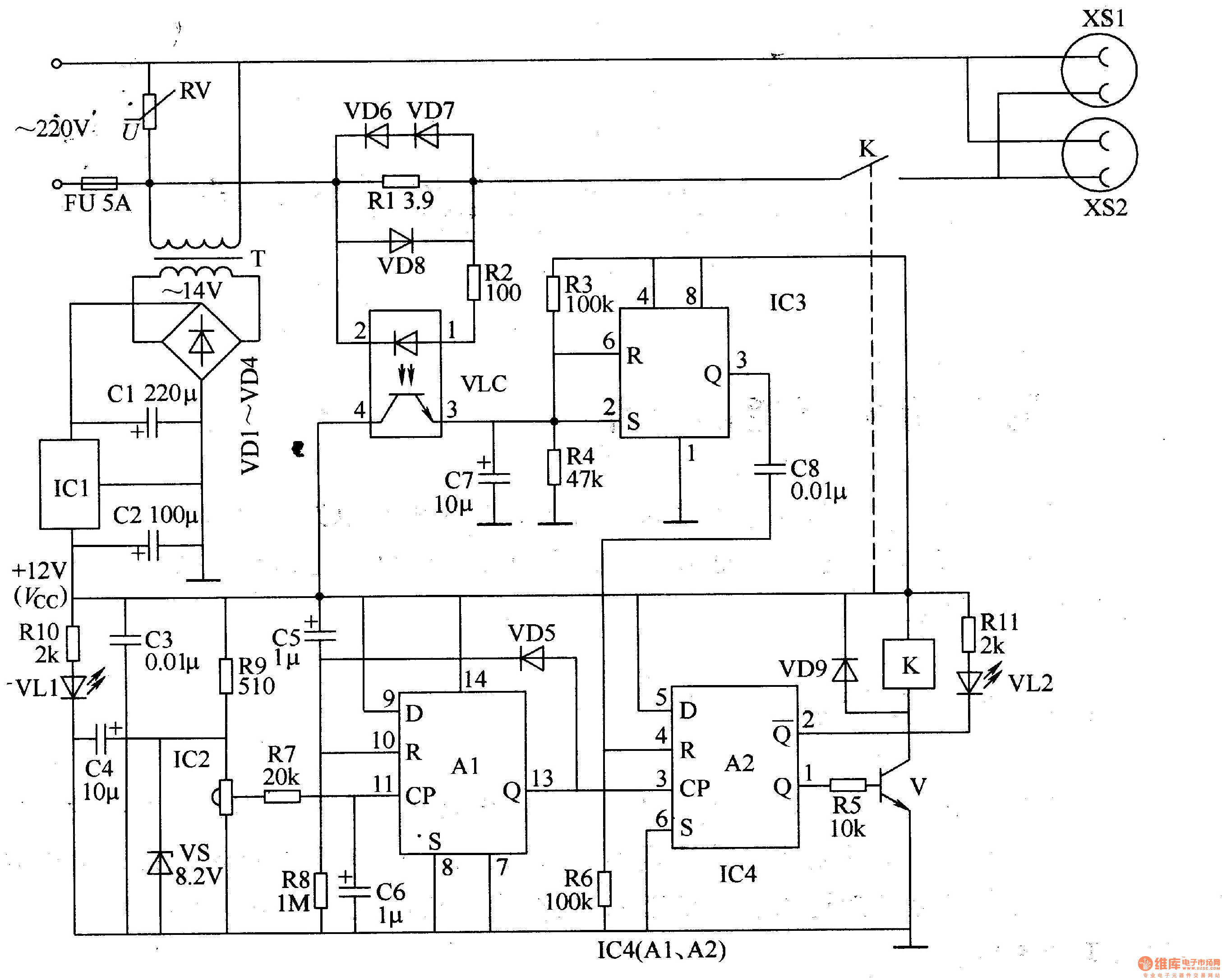
The power circuit consists of fuse FU, varistor RV, power transformer T, rectifier diode VDl-VD4, three-terminal regulator integrated circuit ICl, filter capacitor Cl-C4, current limiting resistor R9, RlO, Zener diode VS and The power indicator is composed of a light emitting diode VLl.
The power-on control circuit is composed of an integrated infrared receiver 1C2, resistors R7, R8, capacitors C5, C6, a diode VD5, and a D flip-flop A1 inside the double D flip-flop integrated circuit IC4.
The shutdown control circuit is composed of resistors Rl-R4, diodes VD6-VD8, optocoupler TVP, capacitor C7 and time base integrated circuit IC3.
The output control circuit is composed of another D flip-flop A2, a transistor V, a resistor R5, a R6, a R11, a capacitor C8, a relay K, a diode VD9 and a light-emitting diode VL2 inside the IC4.
When using, connect the power plug of the color TV standby energy saver to the mains, and the power plug of the color TV is connected to the output socket XSl or XS2 of the economizer, and the power switch of the color TV should be turned on.
After the AC 220V voltage is stepped down by T, VDl-VD4 rectified, Cl filtered and lCl regulated, +l2V voltage (Vcc) is generated across C2. +l2V voltage is directly supplied to IC3, 1C4 and other circuits; one way is Rg current limited, VS is regulated to +8.2V, and it is used as the working voltage of IC2; the other way is to illuminate VL1 via Rl0.
At the moment of power-on, both pins 13 and 1 of IC4 output a low level, V is not conducting, and K is in a released state. When pressing any button on the color TV remote control (aligning it to the infrared receiver IC2 of the color TV energy saver), the IC2 on the color TV standby energy saver will demodulate the received infrared signal, and the generated pulse signal is from the 11th pin of IC4. Add, so that Al and A2 are triggered by flipping, and the 13th and 1st pins of IC4 output high level, V saturation is turned on, K is connected, and the normally open contact turns on the power of XSl and XS2, and the color TV is energized. Work and enter standby. Then use the remote control to align the color TV to implement the second power-on (the division of the two operations should be within 2s), so that the person can be in normal viewing status. At the same time, the high level output of pin 13 of lC4 is added to pin 10 (reset terminal) via VD5, so that Al is reset to zero, and pin 13 of IC4 is restored to low level, ready for the next boot.
After the color TV is energized, its working current generates a voltage drop across the resistor R1. During a certain half cycle of the AC power supply, the LED and the phototransistor inside the photocoupler VLC are turned on successively, and the +12V voltage is light-sensitive. The transistor charges capacitor C7, so that the voltage of pins 2 and 6 of IC3 is higher than 2Vcc/3, and the 3 pin changes from high level to low level.
When the remote control is turned off by the remote control (so that the color TV is in the normal viewing state and the standby state is in the standby state), the voltage across the R1 is rapidly lowered, so that the LED and the phototransistor inside the TVP are both turned off, and the C7 is discharged through R4, when the voltage of the 2 pin of the lC3 is When it is lower than Vcc/3, its internal circuit is reversed, and the 3 pin changes from low level to high level. The high level pulse is added to IC4's 4 pin (reset terminal) via C8, so that A2 is reset to zero, IC4 The 1 pin is restored to a low level, V is cut off, K is released, and the working power of the color TV is completely disconnected.
VLl lights up after the color TV standby energy saver is powered on; VL2 lights up when the color TV power supply is turned on, and goes out after the color TV is powered off.
Component selection
R1 selects 3-5W cement resistor for use; R2-Rll selects 1/4W or 1/8W metal membrane resistor for use.
RV uses 471 varistor.
Cl selects aluminum electrolytic capacitors with a withstand voltage of 25V; C2, C4 and C7 select aluminum electrolytic capacitors with a withstand voltage of 16V; C5 and C6 select aluminum electrolytic capacitors with a withstand voltage of 5OV; C3 and C8 use monoliths Capacitor or polyester capacitor.
VDl-VD4 and VD6-VD9 select 1N4007 type silicon rectifier diode for use; VD5 selects 1N4148 type silicon switch diode for use.
VS selects lW, 8.2V Zener diode.
Both VLl and VU use high-brightness light-emitting diodes of φ5mm; VLl selects red and VL2 selects green.
V selects S805O or C8050 type silicon NPN transistor.
ICl selects LM7812 type three-terminal integrated voltage regulator; IC2 selects integrated infrared receiving head for color TV; IC3 selects NE555 type time base integrated circuit; IC4 selects CD4013 type double D flip-flop integrated circuit.
VLC uses PC817 or 4N25 optical coupler.
K selects l2V DC relay with contact current capacity greater than lOA.
T selects 3W, the secondary voltage is 14V power transformer.
Mini Circuit breakers, also named as the air switch which have a short for arc extinguishing device. It is a switch role, and also is a automatic protection of low-voltage electrical distribution. Its role is equivalent to the combination of switch. Fuse. Thermal Relay and other electrical components. It mainly used for short circuit and overload protection. Generally, According to the poles, mini Circuit breaker can be divided into 1P , 1P+N , 2P, 3P and 4P.
Miniature Circuit Breaker,Electronics Miniature Circuits Breaker,Automatic Miniature Circuit Breaker,Mini Circuit Breaker,MCB
Wenzhou Korlen Electric Appliances Co., Ltd. , https://www.zjmoldedcasecircuitbreaker.com