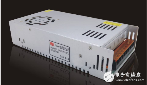
Switching power supply is a kind of power supply that uses modern power electronics technology to control the ratio of time when the switch is turned on and off, and maintains a stable output voltage. The switching power supply is generally composed of a pulse width modulation (PWM) control IC and a MOSFET. With the development and innovation of power electronics technology, switching power supply technology is constantly innovating. At present, switching power supplies are widely used in almost all electronic devices due to their small size, light weight and high efficiency. It is an indispensable power supply method for the rapid development of the electronic information industry.
Switching power supplySwitching power supply is a process in which AC changes to DC, then DC turns into AC, AC and DC. The unstable AC mains is first converted into DC by rectification and filtering, and is used for the operation of the electronic circuit. This circuit includes a high-frequency oscillating circuit, that is, a pulse that converts DC into a variable frequency or pulse width. This part is important in the switching circuit. The input voltage changes or the load increase becomes smaller, and the oscillation circuit maintains the output stability by adjusting the frequency or pulse width. This is its role, in order to play this role, of course, it must start, and the vibration does not indicate that the switching power supply has failed, and there will be no output.
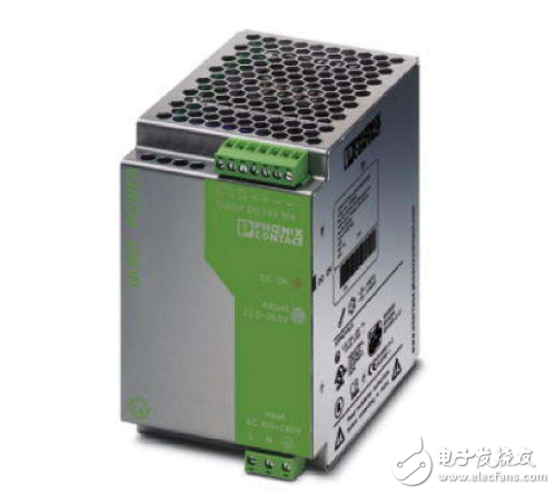
1, the primary (power) voltage is too high or too low
2, start circuit open circuit
3, the power IC power supply pin is shorted or open
4, the power IC is damaged
5, optical coupling short circuit
6, switching transformer turn-to-turn short circuit
7, spike absorption circuit short circuit (power supply with protection function)
8, pulse width modulation tube short circuit (A3 power supply)
9, output short circuit
10, hot end electrolytic capacitor is bad
Switching power supply start-up judgment - false load methodWhen repairing the switching power supply, it is often necessary to disconnect the load in order to take the fault in the load circuit or the power supply itself, and load the test machine at the main output end of the power supply (usually 12V, 18V, or 24V). The reason why the dummy load is to be taken is because the energy stored in the primary winding of the switching transformer is released to the secondary during the cut-off period. If the dummy load is not connected, the energy stored in the switching transformer is not released, which easily leads to the switching of the tube. Wear damaged.
The dummy load is optional: (30.60W) The 12V bulb is used as a dummy load. According to whether the bulb is illuminated or illuminated, it is known whether the power supply has voltage output and output voltage. The advantage is intuitive and convenient. Short-circuit method: The switching power supply of LCD TV adopts the direct sampling regulator control circuit with optocoupler. When the output is high, the short-circuit method can be used to determine the fault range.
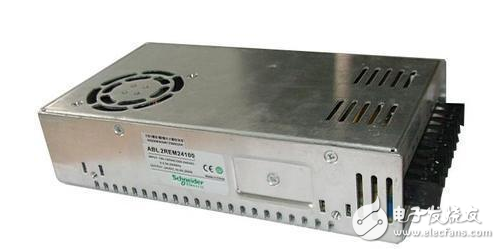
Step: First short-circuit the optocoupler, which is equivalent to reducing the internal resistance of the optocoupler. If the measured mains voltage has not changed, the fault is after the optocoupler, and vice versa, before the optocoupler circuit. (The short circuit method finally disconnects the load).
Switching power supply starting vibration judgment - series bulb methodThe so-called tandem bulb method is to remove the fuse in the input circuit and use a 60W.220V bulb string across the fuse. When the AC power is passed, if the light bulb is very bright, the circuit has a short circuit. Since the bulb has a certain resistance value, such as a 60W/220V bulb, its resistance is about 500 ohms (referred to as thermal resistance), so it can play a certain current limiting effect.
In this way, on the one hand, the brightness of the bulb can be visually judged to roughly judge the fault of the circuit; on the other hand, due to the current limiting action of the bulb, the existing short-circuited circuit is not immediately burned out. The brightness of the bulb will naturally dim until the short-circuit fault is removed. Finally, remove the bulb and replace it with a fuse.
Switching power supply can not be vibration fault repair example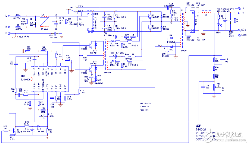
100W instrument switching power supply
The circuit is shown above. The trainees took over 5 or 6 switching power supplies. The faults were not oscillating after power-on. It felt that there was no way to start. Although the power supply for the 3844 chip was already familiar, it still felt a bit of a score. Call me and answer: How to overhaul the 3844, how to repair the power. There are thousands of switching power supply circuits, and the reason is one. Still not a revision? The phone asks again: Where is the start-up circuit? How can I not find the starting resistor? Answer: The starting circuit looks at the picture below.
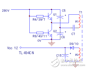
Start-up circuit
The starting resistor is the Q1 (or Q2) base resistor in series with R4, R39, R7 (or R8/40/11). During power-on, due to the difference in characteristics of Q1 and Q2, there must be a tube that conducts first. Anyone who goes through it will cause the inflow current of N1, and then the current/voltage of N2 will be generated. TL494 will work and work.
Q: How do I get started? Answer: Two waves of charge are enough to win. The first wave: From the point of view of insufficient self-power supply (starting energy), C7 and C15 are suspected of major crimes and can be replaced by trials; the second wave, the implementation of starting resistors without dereliction of duty, its behind-the-scenes characters Q1 and Q2 are doubtful ( The magnification is reduced), there may be a tendency to not. No vibration can be used without a third wave of attacks. Pass me orders! Attack immediately, immediately take the 001 high ground!
After a short call back, the news is frequently transmitted: replace Q1, Q2, troubleshooting. The power supply for several years of application is the same reason.
Q1 and Q21 decay, causing the starting current to be insufficient, resulting in a failure that cannot be started. Lian Po, old man, can't eat rice. Although there is no enemy, but there is no retreat, it is also a law.
Switching power supply maintenance essentials1. When repairing the switching power supply, first use a multimeter to check whether the power components are short-circuited, such as the power rectifier bridge, the switch, the high-frequency high-power rectifier; whether the high-power resistor that suppresses the inrush current is blown. Then check whether the resistance of each output voltage port is abnormal. If the above components are damaged, they need to be replaced.
2. After the power is turned on, it still cannot work normally. Then, check the power factor module (PFC) and pulse width modulation component (PWM), check the relevant information, and be familiar with the function of each pin of the PFC and PWM modules and the normal operation of the module. Condition. For a power supply with a PFC circuit, it is necessary to measure whether the voltage across the filter capacitor is about 380 VDC. If there is a voltage of about 380 VDC, the PFC module works normally.
3, in the switching power supply maintenance practice, there are many switching power supplies using UC38 & TImes; & TImes; series 8-pin PWM components, most of the power supply can not work because the power starting resistor is damaged, or the chip performance is degraded, the starting current is increased. In this case, the external circuit connected to the VR terminal is disconnected, the VR changes from 0V to 5V, the PWM component works normally, and the output voltage is normal.
4, switching power supply circuit is easy to have difficulty, the power is large and small, the output voltage is various. As long as you grasp the core things, fully familiar with the basic structure of the switching power supply and the module characteristics, you can quickly eliminate the switching power supply failure.
Our Power Bank have many private model with high quality ABS,glass,Wheat Strawet,we can customize base on your requirements.many ouer power bank have High speed function.
- High Speed Charging Portable iPhone Charger: Highest charge output through 4 USB ports with High Speed
- Polymer Battery: Larger capacity Power Bank and smaller size. Exquisite and portable, handheld size in High capacity. 10000mAh/5000mAh etc.Portable iPhone Charger: Fully charge your iPhone 6s Plus 7.2 times or Galaxy S7 6.6 times or iPad Mini 3 times. Please be fully charged for the first time
- Built in LED Flashlights: This portable charger power bank has a built in LED flash light which is bright enough to help in emergency situations. Built-in Li-polymer ensures definitely safe, metal body prevents from dust, knocking, dropping and more
-
Advance Safety Functions: Our portable backup battery charger is designed to protect your device. The smart circuitry ensures protection against overcharging, short-circuiting, voltage instabilities, and even over discharging


Power Bank,Portable Charger Power Bank,Universal Portable Power Bank,Mobile Phone Power Bank
Shenzhen GEME electronics Co,.Ltd , https://www.gemesz.com