Abstract: This paper discusses the effect of torque compensation on the low speed operation of the compressor through the comparison test of single rotor compressor at low speed. The test results show that by adding the low-speed torque compensation function to the IRMCF171 chip motor control algorithm, the speed fluctuation can be effectively suppressed, and the compressor motor can be prevented from being out of step, while reducing noise and vibration. The single-rotor compressor adds a torque compensation function to the air conditioning application to provide a comfortable and quiet environment for the user.
introductionWhen the operating speed of the air-conditioner single-rotor compressor is low, since the compressor is one inhalation-compression-exhaustion process, the load torque has a large change in one mechanical cycle. And the delay of the speed loop (PI regulator) will cause the output speed to change. These factors can cause mechanical vibration and noise in the system. To solve this problem, we can add a feedforward torque reference loop to compensate for changes in load torque.
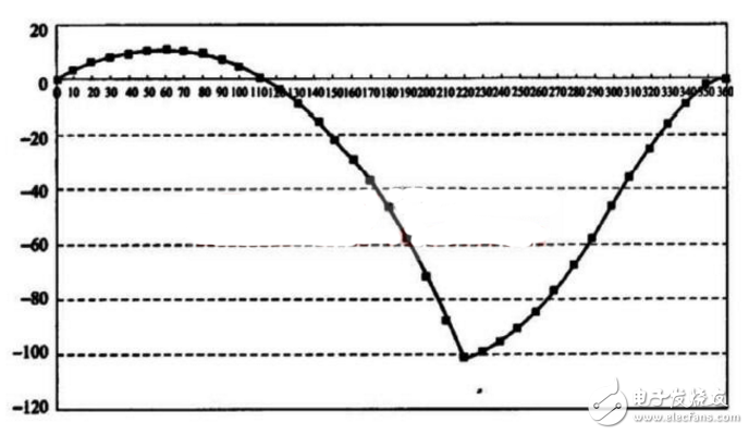
1 Torque compensation principleRegarding the design of the application layer of the IRMCF171 torque compensation function, the basic idea is to first calculate the mechanical cycle from the electrical cycle. Once the mechanical cycle is determined, the compensation curve of the simulated load torque change can be added to the reference torque reference according to the load torque curve during the compressor suction and exhaust process, similar to the sinusoidal curve. Show.
2 Torque compensation algorithm implementationA trigger pulse is generated at the beginning of each electrical cycle, and the start time of each electrical cycle is detected by differentiating the electrical angle, and the trigger pulse is simultaneously transmitted. The effect of this part is to generate a trigger pulse at the beginning of each mechanical cycle. In the case of two pole motors, one trigger pulse is generated for every two electrical cycle pulses. A three-pole motor produces a trigger pulse every three electrical cycle pulses. The high torque segment and the low torque segment are distinguished based on a comparison of the two speed errors before and after. The single-rotor compressor consists of two phases of each mechanical cycle, so the starting point of the mechanical cycle can be determined based on this characteristic.

In the IRMCF171 motor control algorithm, two electrical angle cycles (for two pairs of pole motors) are combined, given a mechanical angle of 0 to 4096. And through vector rotation, an initial phase-adjustable, amplitude-adjustable, sinusoidal torque compensation signal is generated in each mechanical cycle (the single-rotor compressor changes the load torque by approximately one sinusoid per mechanical cycle). ). The initial phase value 0~4096 corresponds to 0-360 degree mechanical angle; the torque amplitude value is 0-4096 corresponding to the torque current given, and 4096 corresponds to the motor rated current peak value.

Torque compensation function use (register configuration):
1) Torque compensation enable zzcountenable: 1 is the start compensation function, 0 is the stop compensation function;
2) initial phase zzangleoffset: set the initial angle of the sinusoidal compensation signal, the value 0~4095 corresponds to the mechanical angle of 0~360 degrees;
3) Compensation torque amplitude zzmagnitude: Set the sinusoidal compensation signal strength, the value 0~4095 corresponds to the motor rated current peak value.
The initial phase and amplitude of the torque compensation can be tested to obtain the best vibration suppression effect. In the debugging, first add a small compensation amplitude, then adjust the initial phase, and use MCEDesigner's waveform tracking function to monitor the speed feedback and observe the compensation effect. Determine an initial phase with a good compensation effect, and then slowly increase the compensation amplitude to observe the final result. Keep the compressor speed and suction and exhaust pressure difference stable during commissioning.
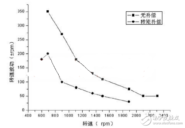
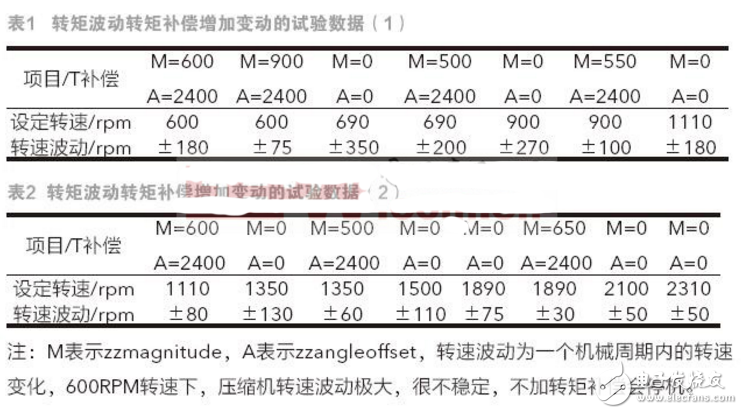
3 test results verificationSeveral speeds were selected from 600~2310RPM for testing. After increasing the torque compensation, the torque ripple was obviously suppressed, especially the speed below 900RPM. Without torque compensation, the speed fluctuation was very large, about ±300RPM.
The test data is shown in Tables 1 and 2.

It can be seen from Fig. 2 that the compressor runs smoothly above 2000 RPM, and the speed fluctuation is significantly increased after the speed is lower than 1200 RPM. After the torque compensation is increased, the speed fluctuation is improved.
The effect of torque compensation on the vibration of the compressor at 1350 RPM is shown in Table 3.

After the torque compensation is increased, the vibration is obviously suppressed, and the reduction is basically about 40%, and the effect is obvious.
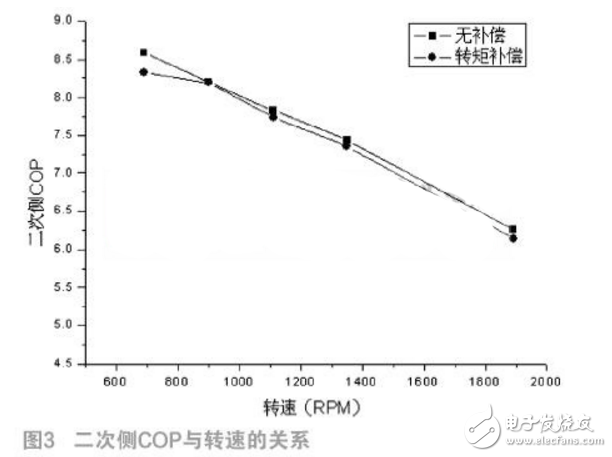
It can be seen from Fig. 3 that after the torque compensation is increased, the energy efficiency ratio of the secondary side is significantly reduced, and the COP is about 3% lower than that without the compensation.

Increasing the torque compensation under the low speed operation of the single rotor compressor can effectively suppress the speed fluctuation, vibration and noise of the compressor, but the addition of the compensation current will increase the input power of the compressor and reduce the energy efficiency ratio.
Marine Power Distribution Cabinet
We are a specialist automation systems integrator with our own well-equipped workshop for building electrical and industrial control panels. Our team use the very latest design and project software, to ensure traceability throughout all steps of the manufacturing process. We constantly invest in the latest electrical control system building equipment, tools, and software.
Every control system is designed to suit your specific application; using only the very best components from leading manufacturers. We are happy to build control panels from your own electrical schematics, or alternatively
The whole Power Distrubtion Cabinet is designed , assembled, testing, programming and site commissioning by our team. Every year we do some projects for power distrubtion cabinets and accumulate rich experience in marine power system.
Being a quality driven firm, we do hard work to serve our customers in a well-systematized & successful way by presenting the optimum grade services. Our offered services are rendered by a crew of creative and talented personnel. We provide these services in accordance with the prevailing industry guidelines and set principles by using contemporary technology. In addition to this, offered services are highly in demand in the market for their outstanding features such as cost effectiveness, hassle free management and timely execution.
Power Distribution Cabinet,Marine Distribution Cabinet,Marine Power Distribution Cabinet,Shipyard Power Distribution Cabinet
Nantong Double Star Automation Equipment Co., Ltd. , https://www.nt-doublestar.com