1. Resonance definition: The energy of the two components L and C in the circuit is equal. When the energy is released by a reactive component in the circuit, and the other reactance component must absorb the same energy, that is, an energy is generated between the two reactance components. pulsation.
2. The circuit must have two components, inductor L and capacitor C, in order to generate resonance.
3. The frequency at which resonance corresponds to is the resonance frequency, or resonance frequency, expressed in fr.
4. The conditions of the series resonant circuit are shown in Figure 1: when Q = Q ⇒ I2XL = I2 XC
When XL =XC, the condition for resonance of the RLC series circuit. 
Figure 1 Series resonant circuit diagram
5. Characteristics of series resonant circuit:
(1) The circuit impedance is the smallest and is a pure resistance. That is, Z = R + jXL - jXC = R
(2) The circuit current is maximum. which is 
(3) The circuit power factor is 1. which is 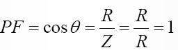
(4) The average power of the circuit is the largest. P=I2R
(5) The total virtual power of the circuit is zero. That is, QL=QC⇒QT=QL−QC=0
6. Frequency of series resonant circuit:
(1) Formula: 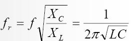
(2) When the R - L - C series circuit is to generate resonance, the power supply frequency f, inductor L or capacitor C can be adjusted.
It is made to reach the resonance frequency fr and is completely independent of the resistance R.
7. The quality factor of the series resonant circuit:
(1) Definition: The ratio of the reactance power generated by an inductor or capacitor at resonance to the average power consumed by a resistor is called the quality factor at resonance.
(2) Formula: 
(3) The higher the quality factor Q value, the better the response of the circuit to resonance. Generally, the Q value is between 10 and 100.
8. The relationship between impedance and frequency of the series resonant circuit is shown in Figure (2):
(1) The resistance R is constant regardless of frequency and is a horizontal line.
(2) The inductance is XL=2 π fL , which is proportional to the frequency, so it is a diagonal line.
(3) Capacitive reactance 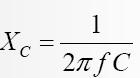
It is inversely proportional to the frequency, so it is a curve.
(4) Impedance Z = R+ j(XL −XC)
When f = fr, Z = R is the minimum value and the circuit is resistive.
When f > fr, XL > XC, the circuit is inductive.
When f < fr, XL < XC , the circuit is capacitive.
When f = 0 or f = ∞, Z = ∞ , the circuit is open.
(5) If the power supply frequency f is increased from small, the change in the circuit impedance Z is first reduced and then increased.
9. The selectivity of the series resonant circuit is shown in Figure (3):
(1) When f = fr, 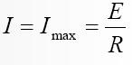
This frequency is called the resonant frequency.
(2) When f = f1 or f 2, 
This frequency is called the sideband frequency, cutoff frequency or half power frequency.
(3) Selectivity of series resonant circuit: the maximum circuit current varies to 
When the maximum current is multiplied, the range between the two adjacent band frequencies is the selectivity of the circuit, which is usually called the bandwidth or the width, and is expressed by BW.
formula: 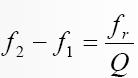
(4) When f = f1 or f2, the circuit power is half of the maximum power, so the cutoff frequency is also called the half power frequency.
formula: 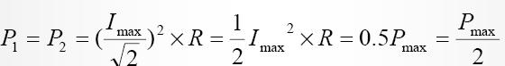
(5) f 2> fr is called the upper cutoff frequency, and f 1 is called the lower cutoff frequency.
formula: 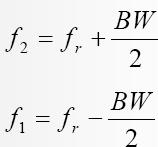
(6) If the power supply frequency f is increased from small, the change of the circuit current I is first increased and then decreased, and the quality factor Q
The larger the value, the sharper the curve, ie the narrower the bandwidth, the better the response and the better the selectivity.
(7) When the bandwidth BW is wide, it means that the quality factor Q is very low; if Q<10, the above formula is not applicable, and the resonant frequency is 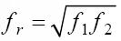
. 
figure 2 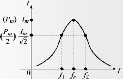
Wire harness & Cable assembly: It is used to transmit data, audio, video, etc. it is a kind of electric energy or signal transmission device, which is usually composed of several wires or groups of wires.
The internal wires are generally used in the internal wires of household appliances, lighting, audio, and instruments, and the internal connection and internal cables of different types of wires.
Wire harness & Cable assembly:It is used to transmit data, audio, video, etc. it is a kind of electric energy or signal transmission device, which is usually composed of several wires or groups of wires.
The internal wires are generally used in the internal wires of household appliances, lighting, audio, and instruments, and the internal connection and internal cables of different types of wires.
Flat cable&Wire harness
ShenZhen Antenk Electronics Co,Ltd , https://www.antenkcon.com