1) A Management Information Base MIB (Management InformaTIon Base). The Management Information Base contains all the parameters of all agent processes that can be queried and modified. RFC 1213 [McCloghrie and Rose 1991] defines the second edition of the MIB, called MIB-II.
2) A common set of structure and representation symbols for the MIB. It is called the Structure of Management InformaTI (SMI). This is defined in RFC 1155 [Rose and McCloghrie 1990]. For example, the SMI definition counter is a non-negative integer whose count range is 0~4294967295. When the maximum value is reached, it starts counting from 0.
3) The communication protocol between the management process and the agent process is called Simple Network Management Protocol (SNMP). Defined in RFC 1157 [Case et al. 1990]. SNMP includes the format of datagram exchange, and the like. Although a variety of protocols can be used at the transport layer, the most used protocol in SNMP is UDP.
Simple Network Management Protocol (SNMP) is a set of network management protocols defined by the Internet Engineering Task Force (IETF). The protocol is based on the Simple Gateway Monitor Protocol (SGMP). With SNMP, a management station can remotely manage all network devices that support this protocol, including monitoring network status, modifying network device configuration, and receiving network event alerts. Although SNMP was originally developed for IP-based network management, it was successfully used as an industry standard for telephone network management.
Second, the history of SNMP developmentSNMP has undergone a relatively long development process and has gone through three versions so far. The most widely used of the moment is SNMPv2.
In 1989, the first version of SNMP was released, called SNMPv1.
In 1991, a supplement to SNMP was released - RMON (Remote Network Monitoring). RMON extends the capabilities of SNMP, including the management of LANs and the management of devices attached to them. Note: RMON does not modify and add the SNMP protocol itself and SMI. It only increases the ability of SNMP to monitor subnets, and monitors the entire subnet as an individual, providing a new MIB library and related MIB behavior.
An upgraded version of SNMPv1 was introduced in 1993, SNMPv2.
In 1995, SNMPv2 was officially released. v2 added the function of SNMPv1 and specified how to use SNMP in OSI-based networks. At the same time RMON expanded to RMONv2 this year.
In 1998, SNMPv3 was released. A series of documents defined the security of SNMP and defined the overall structure of future improvements. SNMPv3 can be used with v2 and v1.
Third, the working principle of SNMPSNMP uses a special client/server model, the agent/management station model. The management and maintenance of the network is done through the interaction between the management workstation and the SNMP agent. Each SNMP slave agent is responsible for answering various queries from the SNMP management station (master agent) regarding MIB definition information.
The application scenario of SNMP is shown in Figure 1:
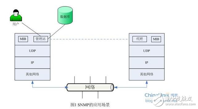
The management station and the agent use the MIB for interface unification, and the MIB defines the managed objects in the device. Both the management station and the agent implement the corresponding MIB object, so that both parties can identify each other's data and implement communication. The management station requests the data defined in the MIB from the agent, and after the agent recognizes, converts the related state or parameter data provided by the management device into a format defined by the MIB, and finally returns the information to the management station to complete a management operation.
Fourth, SNMP message typeFive message types are defined in SNMP: Get-Request, Get-Response, Get-Next-Request, Set-Request, and Trap.
(1) Get-Request, Get-Next-Request, and Get-Response
The SNMP management station retrieves information from the network device that owns the SNMP agent using the Get-Request message, while the SNMP agent responds with a Get-Response message. Get-Next-Request is used in combination with Get-Request to query column elements in a specific table object.
(2) Set-Request
The SNMP management station uses Set-Request to remotely configure network devices (including device name, device attributes, delete devices, or enable/disable a device attribute).
(3)Trap
The SNMP agent sends a non-request message to the SNMP management station, which is used to describe the occurrence of an event, such as the interface UP/DOWN and IP address change.
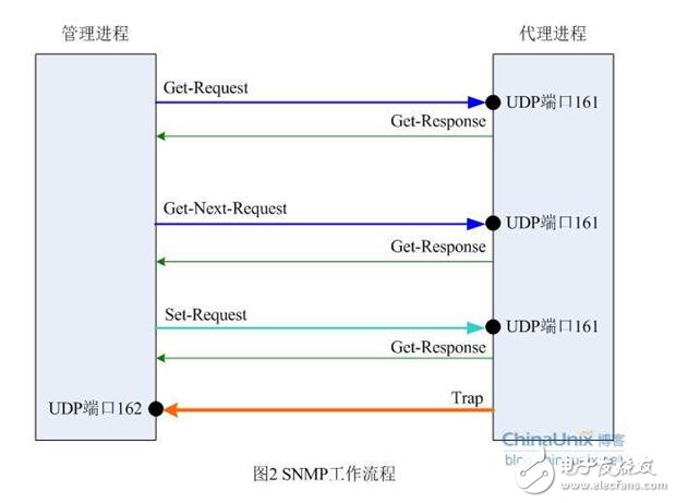
Among the above five kinds of messages, Get-Request, Get-Next-Request and Set-Request are sent by the management station to port 161 of the agent side; the latter two Get-Response and Trap are sent by the agent process to the management process, wherein The Trap message is sent to port 162 of the management process, and all data is UDP encapsulated. The SNMP workflow is shown in Figure 2:
V. SNMP message format
The SNMP agent and the management station communicate via standard messages in the SNMP protocol, each message being a separate datagram. SNMP uses UDP (User Datagram Protocol) as the Layer 4 protocol (Transport Protocol) for connectionless operation. An SNMP message message consists of two parts: an SNMP header and a protocol data unit PDU.

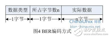
In an actual network transmission environment, the length of an SNMP packet depends on the encoding method used. SNMP uses BER (Basic Encoding Rule) encoding rules, and the ASN.1 syntax is used in the official SNMP specification. Abastract Syntax NotaTIon v1 is the abstract syntax description language. These two concepts will be further introduced in the later practice, so we only need to know a little about it, and it does not hinder our analysis of the agreement itself. Here we briefly explain the BER encoding rules:
BER, as the basic coding rule of ANS.1, describes how a specific ANS.1 object is encoded as a bitstream for transmission over the network. The BER encoding rule consists of three parts:
There are several basic data types defined in SNMP, some of which are changed in v1 and v2. For details, see the corresponding RFC documentation. Here we only introduce some of the most common types:
l INTEGER: an integer
l OCTER STRING: 0 or more 8-bit bytes, each byte takes values ​​from 0 to 255
l DisplayString: 0 or more 8 bit bytes, each byte must be ASCII code. In MIB-II, all variables of this type cannot exceed 255 characters (0 characters can be)
l NULL: represents the relevant variable has no value
l IpAddress: 4-byte long OCTER STRING, which represents the IP address in network byte order.
l PhyAddress: 6-byte OCTER STRING, representing the physical address
l Counter: A non-negative integer that can be incremented from 0 to 232-1(). Return to 0 after reaching the maximum value
l TImeTicks: The time counter is incremented by 0.01 second. Different variables can have different increments. So when defining this type of variable, you need to make an incremental range.
l SEQUENCE: similar to the structure in C language
l SEQUENCE OF: a vector, see the ANS.1 syntax details section later
SNMP packets are encapsulated in UDP packets at the transport layer, and UDP is based on IP networks. Therefore, we can get a complete packet description structure, as shown in the following figure:
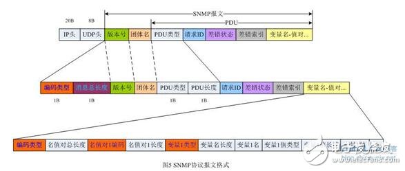
The PDU type actually contains two bytes. The first byte indicates the type of the real PDU; the second byte indicates the total number of bytes in the subsequent message. For SNMPv1, the value of this field is as follows:
Table 1 PDU type
PDU type name proxy process initializes itself
An interface of 1warmStart has changed from working state to fault state (the first variable in the message identifies this interface)
3linkUp received an invalid community message from the SNMP management process
5egpNeighborLoss address)
6enterpriseSpecific "span times=""" new=" roman";="" mso-hansi-font-family:"times""" roman";mso-bidi-font-family:"times=" mso-font- Kerning:0pt "="" style="word-wrap: break-word; font-size: 9pt; font-family: Arial; "" find trap information in this particular code snippet
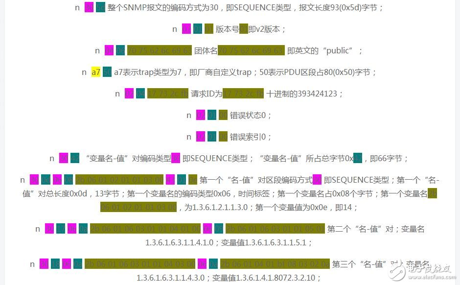
Capture the following SNMP message through the wireshark packet capture tool, and then analyze it carefully.
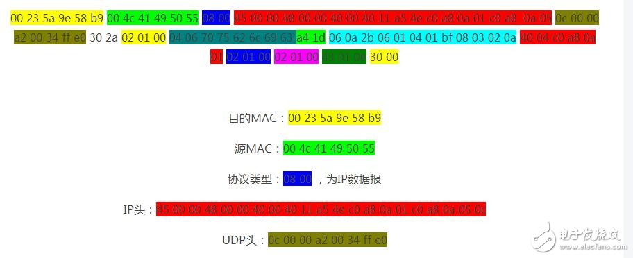
The rest are SNMP messages, and then we analyze them one by one against the previous message structure.
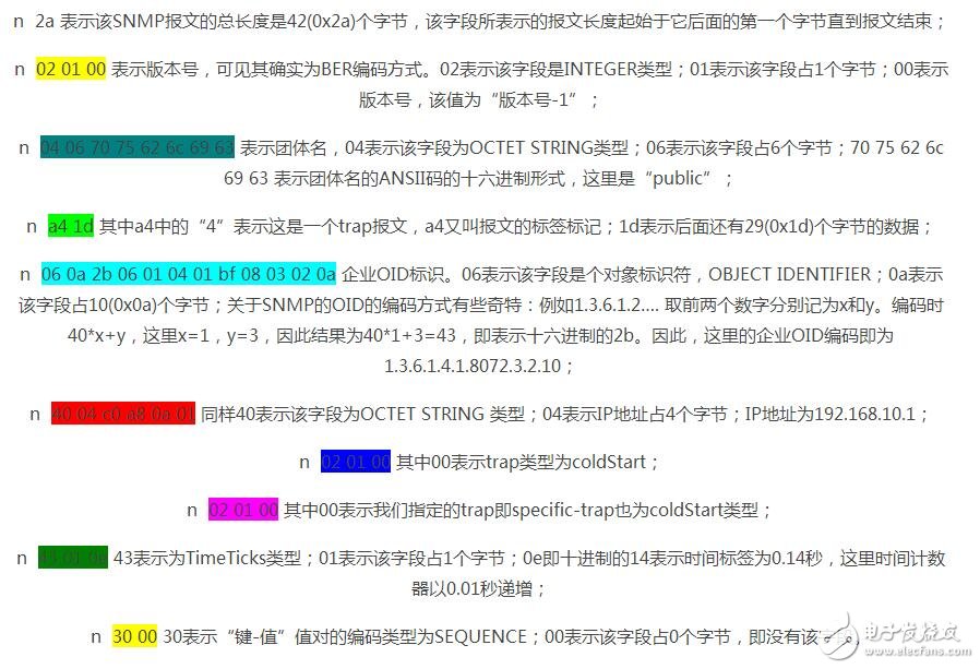
SNMPv2 trap packet
The format of the SNMPv2 Trap packet is shown in Figure 8.

Similarly, except that the trap type and the packet length are standard network byte order, the remaining protocol fields are also BER encoding. You can see that the v2 version of the trap packet is being developed to the unified packet format. It is very similar to the normal SNMP request and response packets.
SNMPv2 original message content:
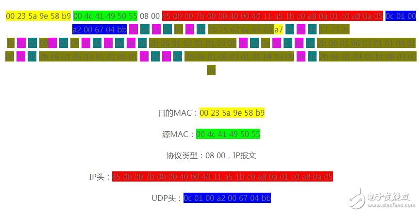
The rest of the content is all SNMP message content, here we make a simple convention:
Xx label type; xx label length; xx label real data.
In this way, the above raw data is analyzed more.
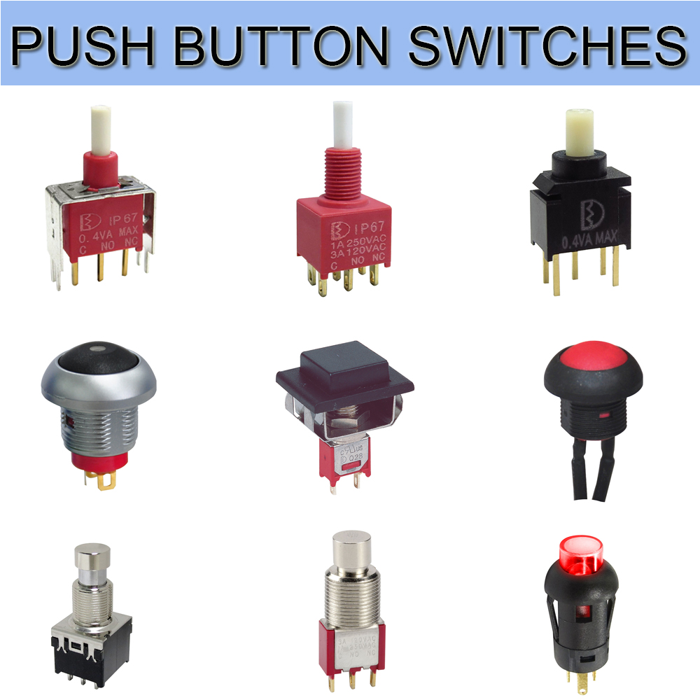
Push Button Switches
The Push Button Switches, also known as the control button (referred to as the button), is a low-voltage electrical appliance that is manually and generally can be automatically reset. The Push Button Starter Switch is usually used to issue a start or stop command in the circuit to control the turning on and off of electrical coil currents such as electromagnetic starters, connectors, and relays.
The On Off Push Button Switches refers to a switch that pushes the transmission mechanism with a button to make the movable contact and the static contact open or close and realize circuit switching. It is a master control device with a simple structure and a wide range of applications. In the electrical automatic control circuit, used to manually send control signals to control connectors, relays, electromagnetic starters, etc.
This Pushbutton Switches is a kind of electric device that is used to switch on and off the small current circuit when the action is released. Generally used in AC and DC voltage below 440V, the current is less than 5A in the control circuit, generally do not directly manipulate the main circuit can also be used in the interconnection circuit. In actual use, in order to prevent desperation, different marks are usually made on the buttons or painted with different colors, and the colors are red, yellow, blue, white, black, green, and the like.

The Momentary Push Button Switch could be divided into metal push button switches and LED Light Switches and ordinary snap button type, mushroom head type, self-locking type, self-resetting type, rotary handle type, with indicator light type, lighted symbol type and key type, etc., with single button and double Buttons. Generally, it adopts a water-storage structure, which consists of a button cap, a return spring, a static contact, a moving contact and a casing. It is usually made into a composite type, and has a pair of normally closed contacts and normally open contacts, and some products can pass. The series connection of multiple elements increases the number of contact pairs. There is also a self-contained button that automatically holds the closed position when pressed, and can be turned on only after the power is turned off.
When the Metal Switches is not pressed, the movable contact is connected with the upper stationary contact. The pair of contacts is called a normally closed contact. At this point, the movable contact is disconnected from the following static contact. The pair of contacts is called a normally open contact: the button is pressed, the normally closed contact is open, the normally open contact is closed, and the button is released. Restore the original working state under the action of the return spring
Push Button Switches,Push Button On Off Switch,Push Button Switch Types,Square Push Button Switches
YESWITCH ELECTRONICS CO., LTD. , https://www.yeswitches.com