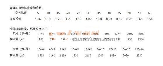
The derating is to make the stress in the use of components lower than its rated value, so as to delay the degradation of the parameters, increase the working life, and improve the reliability of use. With a metaphor that better understands, a person who can walk 100 pounds to walk, let him back 30 pounds hurry away than let him walk 100 pounds to walk a long time away, long distance, the road encountered a gap, can carry 30 pounds back can jump If you go away, you will lose 100 pounds and you will fall easily.
This paper first introduces the reasons and principles for the derating design of the inverter, and then elaborates the reliability choice of the design scheme.
The reason for the derating design of the inverterThe derating design is to make the work stress that the component work under is properly lower than the rated value that the component stipulates, thus reduce the failure rate, improve the reliability. Practice has proved that the appropriate derating of certain parameters of the components can greatly improve the reliability of the components. The temperature is reduced by 10°C and the failure rate of the components can be reduced by more than half. Because the reliability of electronic products is sensitive to its electrical stress and temperature stress, derating design technology and thermal design technology are particularly important for electronic products. It is an integral part of reliability design.
For all kinds of electronic components, it has its best derating range. In this range, the change of working stress has a significant impact on its failure rate. It is also easier to implement in design, and will not be in the product volume and weight. And it costs too much for the cost. Of course, excessive derating is not beneficial, which can cause the characteristics of the components to occur or lead to an unnecessary increase in the number of components or the failure to find a suitable component, but adversely affect the normal operation and reliability of the product.
Three levels of derating design
Derating level: Within the range of the best derating, it is generally divided into 3 derating levels:
Class I is the largest derating and is applicable to derating designs where equipment failures would jeopardize safety and lead to mission failures and severe economic losses. It is the maximum deduction necessary to ensure the reliability of the equipment. If a larger derating is used than this, not only will the reliability of the equipment not increase any more, but it will be unacceptable in design.
Class II derating is a moderate derating and is applied to equipment design where equipment failure will degrade work tasks and unreasonable maintenance costs. This level of derating is still within the scope of reducing the work stress can have a significant effect on the reliability of the equipment growth, it is easier to achieve than the level I derating.
Class III derating is the smallest derating and applies to equipment failures that have only a small impact on task completion and can be economically repaired. This level of derating reliability has the greatest effect, and there is no difficulty in design.
All kinds of components and parts have an optimal derating range. In this range, stress changes have a great influence on the failure rate. Excessive derating is also not desirable, increasing the number of components; after a certain degree of derating, the reliability improvement is very small; excessive derating is harmful: high-power transistor under a small current, greatly reducing the amplification factor and parameters Reduced stability; relay wire package current can not only not reduce, but should be above the rated value, otherwise affect the reliable contact; electric stress derating is easy, the temperature derating, mainly rely on thermal design; derating to improve reliability, but Consider the issues of reliability, size, weight, and cost.
The derating is divided into three grades, and the derating is the largest. It applies to situations where failures endanger safety, lead to task failures and cause major economic losses. Level II derating is centered and is applicable to failures to downgrade tasks and increase unreasonable maintenance costs; Class III derating is minimal, suitable for faults that have little or no effect on mission completion. The main factors for derating are electrical stress and temperature. Electrical stress we consider is much more, the temperature is often considered, but the recessive temperature conditions are often ignored, such as the ambient temperature is 40 °C, the heat inside the chassis is not good, the temperature will certainly If there is equipment around the equipment, it will heat up during work and it will also cause the temperature to rise. This part is a recessive temperature condition, and it is also a reference condition for derating.
The classification of derating levels provides ideas for system design and design management. At the beginning of project design, decentralized coefficients and various components of the entire system are determined to determine appropriate derating levels, and corresponding deductions are then found based on relevant standards. Coefficient, because some specific industry design requirements have their own special requirements, can be determined according to the requirements of the special standard, derating parameters to select the general electrical stress and thermal stress, the mechanical parts and torque, etc., the stress size directly affects the rate of failure High and low, but not necessarily just the main performance indicators only need to derate, to use the conditions of the environment to analyze, determine which indicators are affected by stress conditions. For example, with 220V input capacitance to ground, withstand voltage is a derating indicator, and another safety related leakage current indicator is also necessary to consider.
Design choice reliability500KW inverter, there are many choices for IGBT arrangement, each has advantages and disadvantages.
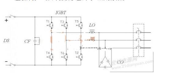
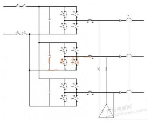
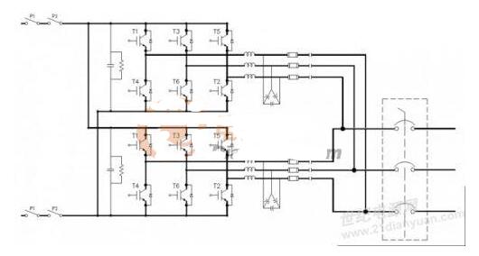
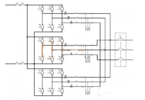
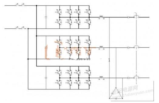
In summary, there are four types, IGBT single module, parallel connection, parallel connection of inverter bridges, and hybrid parallel connection.
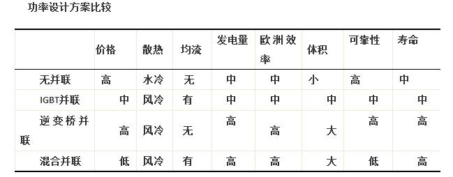
(1) Using 6 single-tube IGBTs, type FZ2400R12HP4, after calculation, each IGBT loss is 1932W, the total loss is 11592W, this method has the advantages of simple circuit, convenient structure design, small volume, high power density, electrical There are no problems such as IGBT current sharing and inverter bridge current sharing. There are only 3 driver chips; the disadvantage is that IGBT prices are relatively expensive and the heat source is relatively concentrated. If the temperature of the heat sink does not exceed 85°C, the heat resistance of the heat sink is 0.02. K/W, radiators that use water-cooled radiators or heating tubes to meet the requirements, the cost is relatively high, only one inductor and filter capacitor, at low power, THD is relatively large, the overall power generation is relatively low.
(2) Divided into two 250KW inverter parallels, each phase has only one power device, 500K inverter selects FF1400R12IP4, DC power is inverted, each receives an LC filter, AC contactor, and then merges into the power grid. An inverter rectangle can be controlled individually. When the input power is less than 45%, one of them can be turned off. The European efficiency is relatively high, the THD is relatively small at low load, the overall power generation is increased, and it can generate electricity when the solar irradiance is low on rainy days. .
(3) IGBT parallel connection scheme. Each bridge arm is connected in parallel with two IGBTs. The inverter uses only one set of LC filter. This method has a lower total cost and higher power density. The disadvantage is that there is IGBT current sharing. When the IGBTs are used in parallel, due to inconsistent power devices, the IGBT driving circuit may not be consistent in its characteristics, and may affect the circuit layout, which may cause unbalanced currents flowing through the parallel IGBTs. Devices with large currents may be overheated. damage. In practical applications, the following measures should be taken: The same batch of devices should be used to reduce the inconsistency of device parameters and improve the effect of static current sharing; share one-way drive circuits to improve device parameter consistency and improve dynamics.
Comparison of Parallel Connection of IGBT and Inverter Bridge
(1) Efficiency comparison: The maximum efficiency IGBT parallel scheme is high, and the European efficiency inverter bridge parallel scheme is high. The total power generation inverter bridge is connected in parallel.
(2) Control method: 6 sets of PWM are required for IGBT parallel connection, and 12 sets of PWM are required for parallel connection of inverter bridge.
(3) Current sharing: IGBTs are connected in parallel to consider the current sharing between devices, which is mainly realized by hardware, and the cost is relatively high. The parallel connection of inverter bridges needs to consider the current sharing between the inverter bridges, which is mainly realized by software.
(4) Portability: IGBTs connected in parallel with 250K, 500K, 750K can not be transplanted, and need to be re-developed. Inverter bridges can be transplanted in parallel, and inverter bridges can be shared.
(5) Structure: IGBTs need 3 heat sinks in parallel, the distance between the three phases is longer and asymmetric, the cost is slightly lower; the modules need 6 radiators in parallel, and the distance between the three phases is shorter. The symmetry is good and the cost is slightly higher. .
Photovoltaic inverters consist of resistors, capacitors, relays, connectors, semiconductor devices, and integrated circuits. In addition to the reliability of the system depends on the inherent reliability of these electronic components, but also with the design of the components can be a reasonable choice.
The selection of components must follow the following principles:
1) In the case of a large number of component types and specifications, the components of the corresponding type, model specification and quality grade should be selected based on the functional requirements and environmental conditions to be achieved by the product.
2) Estimate the stress conditions of the components when they are used, determine the limit values ​​of the components, and use derating design techniques and components.
3) According to the reliability grade of the product requirements, choose the A, B, C components that meet the requirements of the production license examination.
4) When designing a product, try to use standard components and simplify the variety. This is an important principle for the design of large-scale electronic systems, and it is also a constraint imposed on the components and circuit designers by the overall system.
5) Strict verification is required for non-standard components and approval procedures must be used.
6) Develop component selection manuals and standardize component selection and procurement.
Derating should pay attention to the problem
1) The load stress of some components can not be derated or there is a limit to the maximum derating. For example, the filament voltage of the electronic tube and the pull-in current of the relay wire package cannot be deducted, otherwise the lifetime of the electron tube should be reduced;
2) Some components will not achieve the expected derating effect when they are derated to a certain extent. If the power of the thin film resistor is derated below 10%, when the reverse voltage of the diode is derated to less than 60% of the maximum reverse voltage, the failure rate will not decrease.
3) Derating of some types of capacitors may cause low-level failure, that is, an open-circuit failure occurs when the voltage across the capacitor is too low, that is, the derating can not only reduce the failure rate, but will increase the failure rate.
The selection of the derating coefficient is largely determined by the test data and the environmental factors used by the components. The method for determining the derating factor is as follows:
1) the mathematical model and the relationship between the basic failure rate and temperature, derating coefficient;
2) The derating curve gives the function of the derating coefficient and temperature selected to ensure reliable operation of the component. When the semiconductor junction temperature operating on the derating curve reaches its maximum junction temperature, the failure rate is determined. Still higher;
3) Apply the deduction diagram, that is, below the derating curve, find a deducting curve with a lower semiconductor junction temperature through the test;
4) See the national standard for derating factors for various components.
Power switch tube drive circuit design
The function of the IGBT driver circuit is to isolate and amplify the control signal from the DSP to drive IGBTs and other power devices, and to detect the voltage of the circuit to prevent the IGBT from being damaged due to overvoltage and short circuit of the circuit. Therefore, the driving circuit should meet the following requirements:
(1) In order to reduce the loss of the device, the driver circuit should ensure sufficient conduction and reliable shutdown of the device. The connection between the driver circuit and the IGBT should be as short as possible.
(2) Ensure the electrical isolation between the drive circuit and the main circuit. Since the main circuit is a high voltage and the drive control circuit is a low voltage, the drive signal and the main circuit are required to have no electrical coupling.
(3) It has anti-jamming capability to prevent malfunctions of switching devices under various external disturbances, affecting the total power generation of the inverter, and ensuring the high reliability of the device.
(4) It has reliable protection capability. When the main circuit or drive control circuit fails (such as main circuit over-current, over-voltage and under-voltage of the drive circuit), the drive circuit should quickly block the IGBT's PWM signal and shut down the device. The main protection functions are overcurrent detection and protection, undervoltage detection and protection, temperature detection and protection.
IGBT driver circuit can be divided into three types according to function: single-function type, multi-function type, full-function type.
(1) The single-function driver circuit is composed of a power buffer and an optocoupler, such as the HCLP-3150.
(2) Multi-functional high-power IGBT drive protection circuits, such as HCPL-316J, M57962, VLA500-01, etc.
DC bus capacitor design
Continuous DC current output by the solar module, the inverter bridge adopts high-frequency PWM control, and the output is high-frequency pulse current. Therefore, a direct current supporting capacitor is needed between the inverter bridge and the solar module, which mainly has the following functions:
(1) Providing inverter input current together with solar modules;
(2) Reduce harmonic currents into the grid;
(3) When the machine is emergency stopped in an emergency situation, it can absorb the power switching device to turn off the energy;
(4) In the special conditions, can provide instantaneous peak power;
(5) When the inverter is impacted by the instantaneous peak of the power grid, the inverter can be protected.
Bus capacitor design selection, the following main factors to consider: capacitor rated voltage, capacitor capacity, capacitor ripple current, capacitor installation cooling, capacitor temperature rise and life, etc.
1) Considering the ripple current, the ripple current in the bus capacitance generally takes 0.65 times the IGBT current. The ripple current of all capacitors must be greater than this value.
2) Considering the energy conversion, it is generally necessary to make the capacitor bank provide 0.5 cycles of energy.
3) The voltage of the capacitor must be greater than the highest voltage
When selecting IGBTs, consider whether the rated voltage and rated current are within the permissible range:
Withstanding voltage requirements: When IGBT is turned on and off, it will generate a peak voltage, this voltage is lower than the device's withstand voltage value, otherwise the device will be damaged due to high voltage breakdown; the input voltage range of the inverter is 450VDC To 820VDC, the peak voltage at turn-off is: UCESP (820×1.1+50)×α=1047V
In the formula, the highest voltage that CE end bears of IGBT is 820V, 1.1 is voltage protection coefficient of IGBT, α is safety coefficient, generally take 1.1, 50 as the peak voltage caused by L×(di/dt) . Make UCES≥UCESP and move up to the actual voltage level of the IGBT, taking UCES=1200V.
Safe current: During the IGBT operation, the peak current must be less than the rated current of the IGBT.
Sport Earphone
Sports headphones are the perfect companion when running, jogging, hiking, or working out in the gym – with the right music, you'll have twice as much energy and motivation.Sports headphones need to deliver on several counts. They must be resistant to rain and sweat. They should also be tough enough to cope with the movement of exercise, staying firmly and comfortably in place, even during intense workouts.Sometimes,bose soundsport erabuds,bose sport earbuds are used for sport earphone.

Sport Earphone,Sony Sports Earphones,Earphones for Cycling,Sony Sport Earbuds
Pogo Technology International Ltd , https://www.wisesir.net