It took more than a month to study infrared remote control based on the NEC protocol. The following is a summary of the internship technology.
I. NEC protocol features:
8-bit address and 8-bit command length
Each transfer of address (user code) and command (key value) twice
Modulates the signal by the time interval between bursts (PPM)
38Khz carrier
The period of each bit is 1.12ms (low level) or 2.25ms (high level)
Second, the typical pulse chain of NEC agreement:
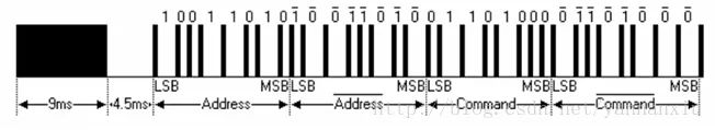
The figure above shows the typical pulse chain of the NEC protocol. The agreement stipulates that the lower bits be sent first. First, the 9ms+4.5ms boot code is sent, followed by the two-byte user code, the third byte is the data code, which is used to determine the key value, the fourth byte is the data anti-code, which can be used to verify, increase the key Accuracy.
Third, the other picture of the NEC protocol pulse chain
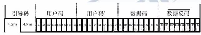
In addition to the boot code, user code, and data code, there is a 1 bit stop bit at the end of the protocol for data transmission completion judgment. In addition, in the NEC protocol, it does not seem to indicate the high and low duration of the stop bit.
Fourth, the high and low levels of the NEC protocol
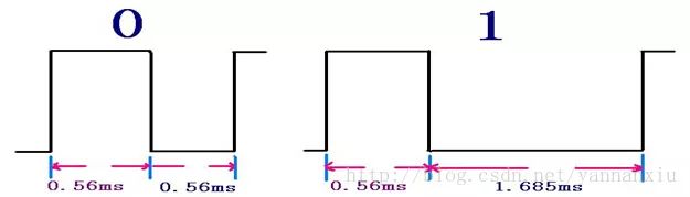
The '0' and '1' in the user code and data code are distinguished by the time interval of the pulse. This encoding method is called pulse position modulation (PPM).
The bit 0 is firstly high for 0.56ms, then low for 0.565ms; bit 1 is first high for 0.56ms, then low for 1.69ms.
Fifth, programming precautions
1. Infrared receiver head pin signal is the opposite level. The above level is from the perspective of the transmitter, the output of the infrared receiver head pin is the opposite level.
As shown in the figure, the P3.2 pin remains high when there is no data transmission. When the data is received, the first is the boot code, 9ms low level and 4.5ms high level, followed by 32-bit data and 1 Stop bit. In general, P3.2 is connected to an interrupt pin of the microcontroller. When receiving data, a low level triggers an interrupt.
2. The data is sent from the LSB (lower bit), so select right shift mode to receive the data.
The four bytes of data are sent D0 first and D7 last. So after receiving 1 bit of data, assign the highest bit to the variable and move it right. Or right shift first and then assign the highest bit of the variable.
3. An array can be used to store the duration of 32 data for later determination of high and low levels.
The time between two data (interrupts) is timed with a timer, and this duration is saved for later determination whether it is bit 1 or bit 0.
4. 32 bytes of data can be stored in 2-byte, 4-byte variables to save code space.
You can use two 16-bit int variables to store data. The first int variable stores the user code, and the second stores the data code and the data. It is also possible to store all data with a 32-bit long variable.
5. Determine the stop bit.
After receiving the stop bit, the IR pin interrupt can be shielded to prevent interference from the following data. After the decoding is successful, the interrupt is enabled.
Induction Cooker,Induction Hob Cooker,Electric Induction Cooker,Induction Wok Cooker
Shandong Sangle Group Co.,Ltd. , https://www.sangle-group.com