As millimeter wave frequencies become more and more popular, how to properly treat such weak cables used at such high frequencies becomes particularly important.
The use of microwave cable assemblies is often arbitrary and unthinkable. However, various incorrect use methods may cause the performance and service life of such cables to decrease. At lower frequencies, due to the larger size of the cables and connectors used, such problems can still be tolerated. However, due to the smaller size of the cables used at millimeter wave frequencies, and generally more vulnerable, their tolerance to cable abuse is also lower.
In the past, the cellular communications industry, which has been operating at a frequency of 3 GHz, will soon adopt a spectrum of 28-100 GHz. In addition, the US Department of Defense (DoD) has increased spending to defend against electronic warfare and radar threats at higher millimeter wave wavelengths. In this way, since millimeter wave-related activities will be more extensive than ever, it is time to review the maintenance and treatment of such critical devices.
Due to the high integration at the above frequencies and the integration of various functions in the same package or circuit board, the number of microwave interconnection devices required may be less. However, even for small base stations and other equipment, the connection of various subsystems still needs to use flexible, semi-flexible, semi-rigid and other cables. In addition, each device and system operating at the above high frequencies must be tested before use, so designers who have not experienced the problem of millimeter wave measurement before will immediately face this challenge.
Test equipment treatmentThe test and measurement environment is one of the few areas where the careful use and maintenance of cables, connectors and components must always be considered important (although in reality people do not fully comply). Since the uncertainty of measurement is a persistent disease of the measurement system, attention to detail is crucial. In addition, because precision vector network analyzers (VNAs) are very expensive to test cables, the cost is another reason that people must be careful about such cables. Since the interconnection devices used at millimeter wave wavelengths are all delicately processed fragile devices, the above situation is equally applicable to all such interconnection devices.
For example, Pastenack's PE3TC1220 series 110GHz test cable assembly is a representative cable assembly used for VNA and semiconductor probe testing (Figure 1). These cable assemblies are provided with 1.0mm male connectors at both ends; Nomex protective armor is used; the insertion loss at 110GHz is below 5.6dB; the typical voltage standing wave ratio (VSWR) is 1.5: 1; the minimum bending at one time bending The radius is 1 inch (2.54 cm); the connector is made of gold-plated beryllium copper and is equipped with a passivated stainless steel coupling nut; there are two lengths of 6 inches (15 cm) and 12 inches (30 cm) to choose from.

1. PE3TC1220 series 110GHz test cable assembly for VNA and semiconductor probe testing
At these frequencies, the importance of treating cables and connectors with caution cannot be overemphasized. The size of the device is wavelength dependent, and the size of the cables (and connectors) used for millimeter wave frequencies is extremely small. From the point of view of size, this is very popular, but for all other aspects of material, manufacturing and performance, it has caused trouble. Such small-sized devices require all users to pay twelve points of care, even tiny dust, almost imperceptible scratches or other damage will damage their measurement accuracy.
For example, the full wavelength of 60 GHz is about 5 mm, and the measurement accuracy of a half-wavelength antenna of this frequency is about 2.5 mm, and a millimeter wave connector with a size of 2.92 to 1.0 mm is used. In addition, people have developed 0.8mm connectors for frequencies above 110GHz. Compared with this type of connector, the connectors used for HF ~ UHF frequencies are huge-the full wavelength of 100MHz is 3m, and the full wavelength of 1GHz is 30cm.
Since loss is an important consideration for millimeter-wave frequencies, the fewer interconnect devices used for the connection between the device under test (DUT) and the measuring instrument and all other components in the transmission chain, the better. In this way, not only can the insertion loss be reduced, but also the number of connection points where there is a risk of disconnection, simplify the test device, and limit the entry path of dust.
The mating process is basic but essentialWhen the millimeter wave cable or connector is mated with the corresponding cable or connector, once it deviates from the correct alignment position, it is easy to cause damage to the center conductor and dielectric layer of the cable or connector. Even slight deviations in the alignment position between the two connectors to be mated may cause adverse effects. The correct approach is to firmly grasp the connector so that it does not rotate, thereby preventing damage to the surface treatment and plating of the contacts, or transmitting torque to the cable assembly. Once the connector is soiled, suspected of damage, uneven pins, excessive torsion damage, or the thread of the coupling nut is damaged, it can no longer be used.
Although few engineers will admit, the use of torque wrenches is not always used to fix the coupling nuts. In some sensitive test and measurement environments, sometimes torque wrenches are even avoided. This is because both novices and veterans want to exercise the "feel" of judging when the connector has been rotated into place. However, once the connector is excessively twisted, the connector will transmit its own error to the corresponding connector and any other connectors mated to it, resulting in an "overall series of errors" in the measurement results.
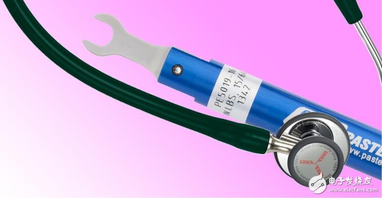
The torque wrench used in the millimeter wave connector is a precision tool. An example here is the PE5019-16 bending torque wrench from Pasternack of the United States, which is used for 1.0mm connectors. Because it is preset to 4 inches pounds (0.45 Newton meters), it can prevent the application of excessive mating force (Figure 2). The advantage of the bending type is that when the preset torque is reached, the bending point will be bent, thereby preventing further force application. The accuracy of the wrench is ± 0.15 inch pounds (0.017 Newton meters), and the hex size is 6 mm.
2. The PE5019-16 torque wrench used for 1.0mm connectors is a bending wrench that eliminates the possibility of excessive twisting of the connector.
Each cable assembly has a maximum bending radius. Once the bending radius is exceeded, the measurement result will be inaccurate and the cable assembly will eventually be damaged. Although in some cases, a large degree of bending may seem inevitable, but once an error occurs, the entire millimeter wave cable can be damaged, so even in this case, it should be avoided as much as possible. In other words, in any case, you should avoid bending the cable to the maximum bending radius.
In addition to this, twisting of the cable should also be avoided, because the twisting may simultaneously cause damage to the cable and damage to the integrity of the components, and sometimes damage to the connector. When wrinkles or other signs of stress are found in the cable jacket, it means that the cable has been severely twisted or its bending radius rating has been exceeded.
Cleanliness is particularly importantIn the case of tight tolerances such as millimeter wave components, all interfaces must be kept clean. Although it may seem extreme, microscopic examination is a good practice. The cleaning process is very simple: find a lint-free cloth (polyester cloth is recommended); use isopropyl alcohol to wet it; use the wet cloth to gently wipe the parts to clean them. In addition, filtered compressed air or nitrogen can also be used. However, it should be noted that the pressurized tank is often filled with a chlorinated solvent for deepening penetration, which may result in gains and losses.
After the above cleaning process is completed, a magnifying glass can be used for surface inspection. When it is necessary to ensure that all metal particles or other substances are removed, the inspection process can also be repeated. Although the magnifying glass is readily available, its effect on interface inspection can be more effective. Possible cable defects include bent pins, missing pins, damaged dielectric layers, worn or damaged threads, and other visually visible damage. Once any such defects are found, the cable must be replaced.
Overall, the improper use of cables used in measurement systems in the aerospace sector is the most severe. This is because only some surveyors in the field understand the correct treatment of cables, while others do not have this awareness. In this field, there are many examples of rough treatment of cables, such as: moving the measurement table by dragging the cable; placing the cable under other objects; pinching, squeezing, stepping on the cable; pulling the cable on the sharp edge ; Often bend the cable beyond its maximum bending radius.
Although the above situation is difficult to eradicate, anyone responsible for the maintenance of the measurement system should at least make every effort to ensure that all cables in use are undamaged. In addition, in the outdoor measurement environment, a "water drop circuit" should also be created for the cable. This is because water droplets can flow into the connector along the cable, which ultimately causes changes in cable performance such as increased insertion loss.
Under aeronautical conditions, the environment of the cable assembly is severe due to the presence of oil and other liquids and gases. Cables should not be directly exposed to such environments, but only cable users may be aware of this. Although the cables in test and measurement applications have a durable design, they do not necessarily have the ability to withstand exposure in all harsh environments.
Various materials can be used for the microwave cable jacket, and each material has its own advantages and disadvantages in harsh environments. For example, polyurethane is resistant to solvents, ultraviolet light, radiation, and fungi, but it is not resistant to cleaning chemicals. Fluorinated polymers such as fluorinated ethylene propylene (FEP), perfluoroalkoxy (PFA) and polytetrafluoroethylene (PTFE) are very suitable for the above environment-they can withstand high temperatures and are exposed to chemicals, acids and intrusive solvents Exposure, and non-flammable substances.
Moisture can oxidize the outer conductor or shield of the cable, which increases the cable loss over time. Therefore, all types of cables regard moisture as a threat. Under RF power, the moisture absorbed by the dielectric layer can be heated up. Water or water vapor can enter the cable through the following places: holes in the jacket material (including very tiny holes); the connection point of the cable and the connector; the mating point of the connector and the corresponding connector.
At the interface between the cable and the connector and between the connector and the connector, a waterproof sleeve may be provided. Even so, water vapor may enter the cable through the tiny wear holes in the cable jacket that can only be observed through a magnifying glass under good light conditions. Therefore, it is necessary to regularly spend a certain amount of time to check the condition of the sheath. Otherwise, as time goes by, the damaged cable will suffer from reduced performance or eventually fail. In addition, there is no doubt that in the shipboard or coastal environment, when the coating is damaged, the salt mist entering the cable can cause corrosion of the metal in the cable, the connector component, or the connector component.
in conclusionOperation at millimeter wave wavelengths is a problem, which is why the development of the millimeter wave band is only for a few applications with suitable characteristics, and these applications rarely involve the communications field.
However, as the cellular communications industry gradually expands to almost all available bandwidth, this situation will change in the next decade. This development, together with the development in the defense field, means that designers must take more stringent precautions than ever before to ensure that their cable assemblies can not only achieve their target performance, but also achieve long-term trouble-free service life.
Electrical Meter Sockets,LCD Power Meter Socket,Digital Power Meter Socket,Power Meter Plug Socket
NINGBO COWELL ELECTRONICS & TECHNOLOGY CO., LTD , https://www.cowellsockets.com