In addition to being used as an AC signal amplifier, the triode can also be used as a switch. Strictly speaking, the triode is not exactly the same as the general mechanical contact switch, but it has some features that are not found in mechanical switches.
Figure 1 shows the basic circuit diagram of the triode electronic switch. As can be seen from the figure below, the load resistor is directly connected between the collector of the triode and the power supply, and is located on the loop of the main current of the triode.
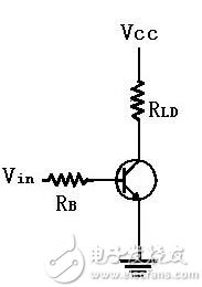
The input voltage Vin controls the open and closed actions of the triode switch. When the triode is turned on, the load current is blocked. Conversely, when the triode is closed, the current can flow. In detail, when Vin is low voltage, since there is no current at the base, there is no current in the collector, so that the load connected to the collector terminal has no current, which is equivalent to the opening of the switch. At this time, the triode is superior to Cut off the area.
Similarly, when Vin is at a high voltage, since the base current flows, the collector flows through a larger amplification current, so the load circuit is turned on, which is equivalent to the closing of the switch, and the triode is superior. In the saturation zone (saturation).
The analysis design of the triode switching circuit is based on the fact that the forward bias voltage of the base emitter junction is about 0.6 volts for the silicon triode. Therefore, in order to turn off the triode, Vin must be lower than 0.6 volt to make the base of the triode. The pole current is zero. Usually at the time of design, in order to be more certain that the triode must be in the off state, the Vin value is often less than 0.3 volts. (838 electronic resources) Of course, the closer the input voltage is to zero volts, the more the transistor switch will be in the off state. To deliver current to the load, the collector and emitter of the transistor must be shorted, just like the closing action of a mechanical switch. In order to achieve this, Vin must reach a high enough level to drive the triode into the saturation working area. When the triode is saturated, the collector current is quite large, almost making the entire power supply voltage Vcc across the load resistance. Then VcE is close to 0, and the collector and emitter of the transistor are almost short-circuited. Under ideal conditions, according to the Ohm's law, the collector current should be:

Therefore, the base current should be at least:

The above equation shows the basic relationship between IC and IB. The β value in the equation represents the DC current gain of the triode. For some triodes, there is a big difference between the AC β value and the DC β value. To make the switch closed, its Vin value must be high enough to deliver a minimum base current value that is greater than or equal to that required by Equation 1. Since the base circuit is only a series circuit of a resistor and a base emitter junction, Vin can be solved by:
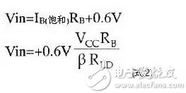
Once the base voltage exceeds or is equal to the value obtained by Equation (2), the transistor is turned on, causing all of the supply voltage to straddle the load resistor, completing the closing action of the switch.
In summary, after the triode is connected to the circuit of Figure 1, its function is the same as a mechanical switch connected in series with the load, and its way of opening and closing the switch can be directly controlled by the input voltage without using Mechanical actuators commonly used in mechanical actuators, solenoid plungers or relay armatures.
In order to avoid confusion, the triode switches described in this article use NPN transistors. Of course, NPN transistors can also be used as switches, but they are less common.
Example 1
Explain why the input voltage required to make the switch closed (triode saturation) in the switching circuit of Figure 2? And explain the load current and base current value solution at this time: It can be known from Equation 2 that in the saturated state, all the supply voltages completely fall across the load resistance, so

Known by equation (1)

Therefore, the input voltage can be obtained by:
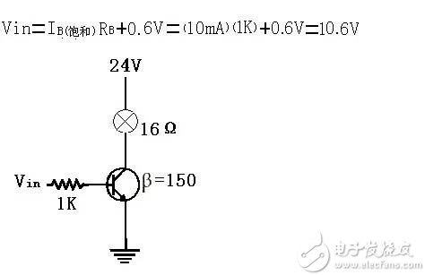
Figure 2 Using a triode as a light bulb switch
According to the example 1-1, it is only necessary to use a small control voltage and current to control the opening and closing action of the load current up to 1.5A by using the triode switch. In addition, although the triode flows a large current, it does not need to be equipped with a heat sink, because when the load current flows, the triode is saturated, and its VCE approaches zero, so the power multiplied by the current and voltage is very small. No heat sink is required.
Comparison of Transistor Switch and Mechanical Switch So far, we have assumed that when the triode switch is turned on, its base and emitter are completely short-circuited. This is not the case. No triode can be completely shorted to VCE=0. Most small-signal silicon transistors have a VCE (saturation) value of about 0.2 volts when saturated, even though they are designed for switching applications. Its VCE (saturation) value can only be as low as about 0.1 volts, and the load current is high, and the VCE (saturation) value will rise slightly, although for most analytical calculations, VCE (saturation) Values ​​can be disregarded, but when testing switched circuits, it must be understood that the VCE (saturation) value is not really zero.
Although the voltage of VCE (saturated) is very small, it is insignificant in itself. However, if several triode switches are connected in series, the sum of the voltage drop effects is considerable. Unfortunately, mechanical switches are often connected in series. Working, as shown in Fig. 3(a), the triode switch cannot simulate the equivalent circuit of the mechanical switch (as shown in Fig. 3(b)), which is a major disadvantage of the triode switch.
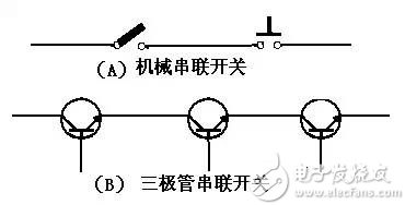
Figure 3 Transistor switch and mechanical switch circuit
Fortunately, although the triode switch is not suitable for the serial connection method, it can be perfectly applied to the parallel connection mode, as shown in Figure 4. Compared with traditional mechanical switches, triode switches have the following four advantages:
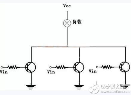
Figure 4 parallel connection of the triode switch
(1) The triode switch does not have the movable contact part, so it can be used without any wear and tear. It can be used infinitely many times. The general mechanical switch can only use millions of times at most due to the wear of the contact, and its contact is easy. Stained and affected work, so it can't work in a dirty environment. The triode switch has no contact and is sealed, so there is no such concern.
(2) The operating speed of the triode switch is faster than that of the general switch. The opening and closing time of the general switch is calculated in milliseconds (ms), and the triode switch is measured in microseconds (μs).
(3) The triode switch has no bounce phenomenon. The general mechanical switch will have a fast continuous opening and closing action at the moment of conduction, and then gradually reach a steady state.
(4) When a triode switch is used to drive an inductive load, no spark is generated at the moment the switch is turned on. Conversely, when the mechanical switch is turned on, since the current on the inductive load is cut off instantaneously, the instantaneous induced voltage of the inductor will cause an arc at the contact. This arc will not only erode the surface of the contact, but may also cause interference or harm.
The test of the triode switch is not like the mechanical switch. It can judge the current open and close state by the naked eye, so it must be tested with the electric meter. In the standard triode switching circuit shown in Figure 5, when the switch is turned on, the read value of VEC should be 0, whereas when the switch is turned off, VCE should be for VCC.
When the triode switch is off, there is no current flowing through the load, so there is no voltage drop, so all the supply voltages are across the two ends of the switch, so its VCE value should be equal to VCC, and the mechanical switch is Exactly the same. If the switch itself should be turned on and not turned on, then you have to test the size of Vin. To ensure that the triode is turned on, the Vin voltage of the base must be high enough. If the Vin value is too low, the problem comes from the source rather than the transistor itself. If the level of Vin is high enough, the drive transistor is turned on without any problem, and the load is still not turned on, then test whether the power supply voltage is normal.
In the on state, the VBE value of the silicon triode is about 0.6 volts, if the Vin value is high enough, and the VBE value is higher than and lower than 0.6 volts, for example, VBE is 1.5 volts or 0.2 volts, which means that the base emitter is connected. The face may have been damaged and the transistor must be replaced. Of course, this criterion is not necessarily 100% correct. Many high-current rated power transistors often have a VBE value of more than 1 volt. Therefore, even if the VBE reading reaches 1.5 volts, it is not certain that the junction of the triode is damaged. It is best to consult the triode specification sheet before asserting it.
Once the VBE is normal and there is a base current flowing, the VCE value must be tested. If the VCE approaches VCC, it means that the collector junction of the triode is damaged and the triode must be replaced. If the VCE approaches zero volts and the load is still not conducting, it may be that the load itself has an open circuit, so the load must be checked.
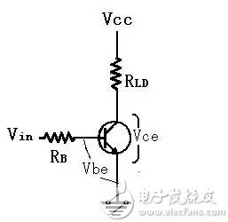
Figure 5 Transistor switching circuit, voltage diagram of each main test circuit
When Vin is reduced to a low voltage level, the three-pole management should be cut off to cut off the load. If the load is still not cut, it may be that the collector base and collector of the triode are short-circuited and must be replaced.
The second section of the basic triode switch improvement circuit Sometimes, the low voltage level we set may not be able to turn off the triode switch, especially when the input level is close to 0.6 volts. In order to overcome this critical situation, it is necessary to take corrective steps to ensure that the triode must be cut off. Figure 6 shows two common improvements in circuit design for this situation.
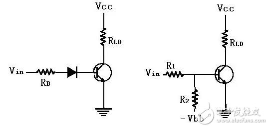
Figure 6 ensures the triode switching action, the correct two improved circuits
The circuit of Figure 6(a) has a diode connected in series between the base emitters, thus increasing the input voltage value that causes the base current to conduct by 0.6 volts, even if the Vin value is close due to the source's malfunction. At 0.6 volts, the transistor is not turned on, so the switch can still be turned off. The circuit of Figure 6(b) adds an auxiliary-off-resistor R2. The appropriate R1, R2, and Vin values ​​are designed to ensure that the switch is turned off at critical input voltages. It can be seen from Fig. 6(b) that before the base emitter junction is not turned on (IB0), R1 and R2 form a series voltage divider circuit, so R1 must cross the fixed voltage (which varies with Vin), so the base The voltage must be lower than the Vin value, so even if Vin is close to the critical value (Vin = 0.6 volts), the base voltage will still be pulled down by the auxiliary-off-resistance connected to the negative supply, making it less than 0.6 volts. Due to the deliberate design of R1, R2 and VBB values, as long as Vin is in the high value range, the base will still have enough voltage to turn on the transistor without being affected by the auxiliary-off-resistance.
Speed-up capacitors
In applications that require fast switching, the switching speed of the triode switch must be increased. Figure 7 is a common way. This method only needs to connect an accelerating capacitor in parallel with the RB resistor. When Vin rises from zero voltage and starts to supply current to the base, the capacitor cannot be instantaneously charged, so it is short-circuited. However, at this time, there is a momentary large current flowing from the capacitor to the base, thus speeding up the conduction of the switch. Later, after the charging is completed, the capacitors are opened in the same way without affecting the normal operation of the triode.
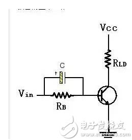
Figure 7 Circuit with acceleration capacitor added
Once the input voltage drops from the high level to the zero voltage level, the capacitor will turn the base emitter junction into a reverse bias in a very short time, and the transistor switch will be quickly cut off. This is because the left end of the capacitor is the original. It has been charged to a positive voltage, as shown in Figure 6-9. Therefore, at the moment when the input voltage drops, the voltage across the capacitor cannot be changed instantaneously and will remain at a constant value, so the drop of the input voltage immediately causes the base voltage to decrease. Therefore, the base emitter junction is reverse biased, and the transistor is quickly turned off. Proper selection of the acceleration capacitor value can reduce the switching time of the triode switch to below a few tens of microseconds. Most of the acceleration capacitor values ​​are about hundreds of picofarads (pF).
Sometimes the load of the triode switch is not directly applied between the collector and the power supply, but is connected to the mode of Figure 8. This connection is very close to the circuit of the small-signal AC amplifier, except that one output coupling capacitor is missing. This connection is exactly the opposite of the normal connection. When the triode is turned off, the load is enabled, and when the triode is turned on, the load is reversed. Both forms of the circuit are common and must be clear. Resolving power.
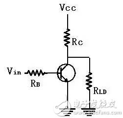
Figure 8 Improved connection of the load to the triode switching circuit
Totem-pole switches
If the triode switch of Figure 8 is added with a capacitive load (assuming it is in parallel with the RLD), then after the triode is turned off, since the load voltage must be slowly charged by the RC resistor, the capacitance or resistance value is increased. The larger the time constant (RC), the slower the rate of rise of the load voltage, which is not acceptable in some applications, so the improved circuit of Figure 9 must be used.
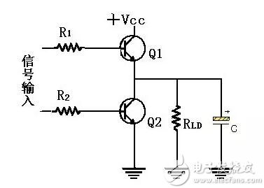
Figure 9 totem transistor switch
The totem-type circuit is constructed by directly superposing a triode on another triode, which is also named after it. In order to enable the load, the Q1 transistor must be turned on and the Q2 transistor can be cut off. Therefore, the load can be connected to the VCC via Q1. To disable the load, the Q1 transistor must be cut off and the Q2 transistor turned on. This load will be grounded via Q2. Since the collector of Q1 has almost no resistance except for the very small contact resistance (as shown in Figure 9), the load is almost directly connected to the positive power supply. Therefore, when Q1 is turned on, there is no longer any The slow charging phenomenon of the capacitor exists. So it can be said that Q1 “pulls up the load†and “pull up the triodeâ€, and Q2 is called the “pull down triodeâ€. The input control circuit in the left half of Figure 9 is responsible for the turn-on and turn-off control of the Q1 and Q2 transistors, but it must be ensured that Q1 and Q2 are not turned on at the same time, otherwise VCC and ground will be short-circuited via Q1 and Q2. If this is the case, the large current of the short circuit will at least burn a triode. Therefore, the totem-type triode switch must not be used in parallel as shown in Figure 6-4. Otherwise, as long as there is any conduction in the Q1 group above the totem, and there is exactly one conduction in the lower Q2 group, the power supply It is short-circuited by the conduction of Q1 and Q2, causing serious consequences.
The third most common application of the transistor switch is to drive the indicator light. The indicator light can indicate the operation status of a certain point of the circuit, and can also indicate whether the controller of the motor is activated. Indicates whether a limit switch is conducting or whether a digital circuit is in a high state.
For example, Figure 10(a) uses a transistor switch to indicate the output state of a digital flip-flop. If the output of the flip-flop is at a high level (typically 5 volts), the transistor switch is turned on and the indicator light is illuminated, so the operator can know the current working condition of the flip-flop as soon as the indicator light is viewed. Without the need to use a meter to detect.
Sometimes the current capacity of the output circuit of the signal source (such as the flip-flop) is too small to drive the transistor switch. In order to avoid the malfunction of the signal source, the improved circuit shown in Figure 10(b) must be used. When the output is at a high level, the emitter is driven by the transistor Q1 for current amplification.
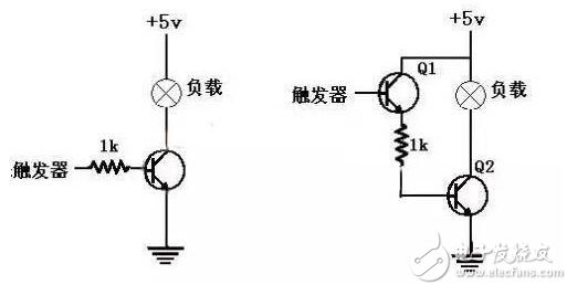
Figure 10 (a) Basic circuit diagram Figure 10 (b) Improved circuit
Then, the Q2 is turned on to drive the indicator light. Since the input impedance of the emitter follower stage is relatively high, the flip-flop requires a small amount of input current to obtain satisfactory operation.
Digital Display The circuit of Figure 10(a) is often used on digital displays.
Using triode switches as interface circuits with different voltage levels In industrial equipment, solid-state logic circuits must often be used for control work. The principle of digital logic circuits will be described in detail in the next chapter. For the first time, the control circuit of industrial equipment is divided into three parts: (1) input part, (2) logic part, and (3) output part.
To achieve reliable operation, the input and output sections of industrial equipment typically operate at higher voltage levels, typically 220 volts. The logic part is operated at a low voltage level. In order for the system to work properly, it is necessary to enable communication between the two different voltage levels. This matching between different voltages is called an interface. )problem. The circuit that serves as the interface matching work is called an interface circuit. Transistor switches are often used to perform such work.
Figure 11 uses a triode switch as an example of an interface circuit that controls low-voltage logic from a high-voltage input. When the input micro-switch is closed, the step-down transformer is turned on, and the full-wave rectification filter circuit sends a low-voltage DC control. A signal that turns the transistor on and the collector voltage drops to zero (saturated) volts. This 0 volt signal can be fed into the logic to indicate that the microswitch is closed.
Conversely, if the micro switch is turned on, the transformer will not be energized, and the transistor will be turned off. At this time, the collector voltage will rise to the VCC value, and the VCC signal can be sent to the logic circuit to indicate that the micro switch is turned on. . In Figure 11, the logic circuit is considered as the load of the triode, connected between the collector and ground (Figure 11), so the R1, R2 and RC values ​​of the triode switching circuit must be carefully selected to ensure that the triode only works. In the cut-off zone and the saturation zone, not in the active (linear) zone.
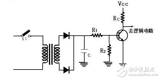
Figure 11 transistor switch as the interface between the input part and the logic part
Speakers are one of the most common output devices used with computer systems. Some speakers are designed to work specifically with computers, while others can be hooked up to any type of sound system. Regardless of their design, the purpose of speakers is to produce audio output that can be heard by the listener.
Speakers are transducers that convert electromagnetic waves into sound waves. The speakers receive audio input from a device such as a computer or an audio receiver. This input may be either in analog or digital form. Analog speakers simply amplify the analog electromagnetic waves into sound waves. Since sound waves are produced in analog form, digital speakers must first convert the digital input to an analog signal, then generate the sound waves.
The sound produced by speakers is defined by frequency and amplitude. The frequency determines how high or low the pitch of the sound is. For example, a soprano singer's voice produces high frequency sound waves, while a bass guitar or kick drum generates sounds in the low frequency range. A speaker system's ability to accurately reproduce sound frequencies is a good indicator of how clear the audio will be. Many speakers include multiple speaker cones for different frequency ranges, which helps produce more accurate sounds for each range. Two-way speakers typically have a tweeter and a mid-range speaker, while three-way speakers have a tweeter, mid-range speaker, and subwoofer.
Speaker System,Magnet Speaker Acoustic,Moving Coil Loudspeaker,Metal Frame Mylar Speaker
Jiangsu Huawha Electronices Co.,Ltd , https://www.hnbuzzer.com