In the air of a region, what are some TV signals, and what is their field strength? This is a topic of concern to the radio and television management departments and the non-committee. This article will discuss from the perspective of electronic measurement.
First, TV signal and its field strengthAs is well known, a television signal is a carrier signal in the range of 42-860 MHz, modulating a video signal and an audio signal. To analyze these signal characteristics, this is the subject of video analysis and audio analysis. However, in terms of the strength of the signal, the line synchronization signal level of the television signal is characterized. Since the line synchronization signal is pulsed, the peak is used as a measure. .
For the field strength measurement and field strength meter authors have been described in another article, please refer to the "field strength measurement and field strength meter" in the Hauge website.
There are two points to be highlighted here:
1. Field strength is the magnitude of an electrical signal induced by a unit length antenna at a point in the air. The unit is microvolts per meter (μV/m), not the voltage or level unit V, μV or dB μV, dBm.
2. The composition of the field strength meter is a level meter (or spectrum analyzer) plus a test antenna. The field strength meter called in the cable TV industry in China generally refers to the TV signal level meter, which is measured by the peak value.
The measurement principle of the air field strength of television signals, as described by the author in the field strength measurement and field strength meter. The measurement box is shown in Figure 1. In view of the characteristics of the TV signal field strength, the level meter should be a TV signal level meter (commonly known as a TV field strength meter), and the antenna should be a measurement antenna in the TV frequency range. . The field strength value E is obtained by the following formula (1).
E=E r+ K + Lf (dBμV/m) —--(1)
among them:
E is the field strength value (dBμV/m)
E r is the meter input port level value (dBμV)
K is the antenna coefficient (dB)
Lf is the connection cable loss value (dB)
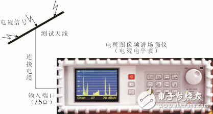
For the TV signal level meter, it is better to have a spectrum analyzer function in addition to the measurement level, which can perform panoramic scanning observation on the signal of the required frequency range, and then press the cursor to lock the signal you need. However, in addition to the TV signal, there are many other signals in the air, such as communication signals, radio signals, and other radio signals. Our task is to observe the TV signal. Then the instrument should also have a TV image display function. Search lock, then you can see the image at the same time, this will actually search all the TV signals in this frequency band, and simultaneously measure its field strength, you can also monitor which TV stations we are under the jurisdiction, whether we have non-governance The TV station appeared.
For the antenna, the frequency range of the antenna should be 46-860MHz and give the K value of the antenna coefficient.
In this way, the field strength meter can be obtained from equation (1). Different antenna manufacturers give positive and negative antenna coefficients. Please pay attention when using them. For example, in this paper, Anli is a K, and domestic 900E is +K.
If the connecting cable is 1 to 2 meters long, it can be ignored, which means that the measured field strength is the meter reading plus the antenna coefficient.
E=E r+ K -------- (2)
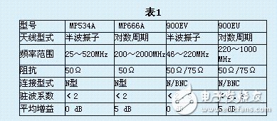
Fig. 2 and Fig. 3 are antennas produced by Anritsu Corporation of Japan. The antenna coefficients K are shown in Fig. 4 and Fig. 5, respectively. MP534A is a half-wave oscillator type, and MP666A is a logarithmic period type. The technical indicators are shown in Table 1.
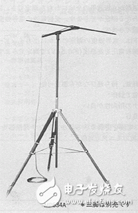
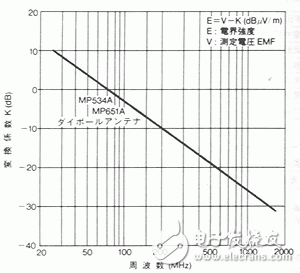
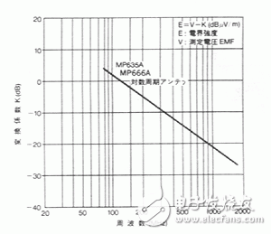
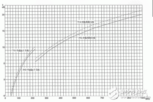
Figure 6 shows a domestic 900E antenna, in which 900EV is a half-wave oscillator type with a frequency of 40-220MHz; 900EU is a logarithmic period type with a frequency of 220-1000MHz. The antenna coefficient is shown in Figure 7, and the technical indicators are shown in Table 1.

Give an example:
The 900E antenna is connected to the PRK3C+ color television image spectrum field strength meter. After the PRK3C+ is turned on, it works in the spectrum analysis state and displays multiple signals. We can move the cursor, search for the signal at 320.25MHz, and then put the instrument in the TV receiving state. When the image is received, the level value can also be read.
Set the level value to 68 dBμV
Look at Figure 7, the horizontal axis is at 320.25MHz, and the vertical axis has a K value of 9 dB.
The field strength is E=68 dBuV+9 dB=77 dBμV/m
1. Measurement accuracy of field strength To measure the air field strength, it is self-evident that the antenna induces an electrical signal at a certain point in the air. First, the antenna measurement is directional, so the antenna must be rotated to take its maximum value.
In terms of its test accuracy, the main sources of error are the instrument and the antenna.
a thing that joins together two parts of sth, two vehicles or two pieces of equipment.
Custom Coupling,Coupling Of Encoders,Useful Coupling,Latest Coupling
Yuheng Optics Co., Ltd.(Changchun) , https://www.yhencoder.com