First, the definition: 1, the pull-up is the signal of uncertainty through a resistor embedded in high! Resistor restricts current at the same time! Pull down the same reason
2. The pull-up is to inject current into the device, the pull-down is the output current 3, and the pull-up resistor has weak resistance. There is no strict discrimination 4. For non-collector (or drain) open-circuit output circuit (such as ordinary door The ability of the circuit to boost current and voltage is limited, and the function of the pull-up resistor is mainly the output current path of the open collector output circuit.
Second, pull the role of resistance: 1, generally used for one-touch trigger, if the IC itself does not have internal resistance, in order to maintain a single key is not triggered or return to the original state after the trigger must be connected outside the IC A resistor. 2. The digital circuit has three states: high level, low level, and high resistance state. In some applications, high resistance state is not desired. It can be in a stable state by pull-up resistor or pull-down resistor, depending on the design requirements. And set!
3, generally speaking I/O ports, some can be set, some can not be set, some are built-in, some need an external, I / O port output is similar to a transistor C, when C connected through a resistor and power supply When connected together, the resistor becomes an upper C pull-up resistor, that is, if the port is normally high and C is connected through a resistor and ground, the resistor is called a pull-down resistor, making the port Normally low, its role is mainly to ensure that a port has a certain level when it is normal: Usage Example: When a port with a pull-up resistor is set to the input state, its normal state is high for detection. Low level input.
4. The pull-up resistor is used to provide current when the bus drive capability is insufficient. The general idea is to pull the current, the pull-down resistor is used to absorb the current, which is what we usually call current.
5. The resistor is connected to prevent the input terminal from floating.
6, weaken the external current on the chip interference.
7, protect the protection diode in cmos, the general electric current is not greater than 10mA.
8. Increase or decrease the drive current by pulling up or down.
9, change the level of potential, commonly used in TTL-CMOS matching.
10, there is a certain state when the pin is floating.
11, increase the high-level output drive capability.
12. Provide current for the OC door.
Third, pull-up resistor application principles: 1, when the TTL circuit drives the COMS circuit, if the TTL circuit output high level is lower than the COMS circuit's lowest high level (usually 3.5V), then you need to be in the TTL output Terminate the pull-up resistor to increase the output high value. Note: At this time, the voltage value of the pull-up resistor should not be lower than the minimum high voltage of the CMOS circuit. At the same time, consider the influence of the square current of the TTL circuit (such as the maximum input or output current of a certain port).
2, OC gate circuit must be pulled resistance to use. 3, in order to increase the output pin's drive capability, some microcontroller pins often use pull-up resistors. 4. On the COMS chip, in order to prevent damage caused by static electricity, unused pins cannot be left unconnected. Generally, the pull-up resistor is used to reduce the input impedance and provide a discharge path. 5. The pin of the chip is added with a pull-up resistor to increase the output level, thereby improving the noise margin of the chip input signal and enhancing the anti-interference ability. 6. Improve the anti-electromagnetic interference capability of the bus. If the pins are vacant, it is easier to accept external electromagnetic interference. 7, the long-line transmission resistance mismatch does not easily cause reflection wave interference, coupled with the pull-down resistor is a resistor matching, effective suppression of reflection wave interference. 8, in the digital circuit, the unused input pin must be connected to a fixed level, connected to the high level or ground through 1k resistor.
Fourth, pull-up resistor resistance selection principle: 1, from saving power and the chip's current sink capacity should be considered large enough; resistance, current is small.
2. It should be sufficiently small to ensure sufficient drive current; the resistance is small and the current is large.
3. For high-speed circuits, excessive pull-up resistors may flatten the edges. Take into account the above three points, usually between 1k and 10k. The same applies to pull-down resistors.
The selection of pull-up resistors and pull-down resistors should be set in conjunction with the switching transistor characteristics and the input characteristics of the lower circuit. The following factors must be considered: 1. The balance between drive capability and power consumption. The above pull-up resistor is used as an example. In general, the smaller the pull-up resistor is, the stronger the driving ability is, but the greater the power consumption, the more attention should be paid to the balance between the two designs. 2, the drive needs of the lower circuit. The same is true for the pull-up resistance. For example, when the output is high, the switch is turned off and the pull-up resistor should be properly selected to provide enough current to the next-stage circuit. 3, high and low settings. The level of the high and low levels of the different circuits will be different, and the resistance should be set appropriately to ensure that the correct level can be output. For the above pull-up resistors, for example, when the output is low, the switch turns on, and the pull-up resistor and the on-resistance of the switch tube should be guaranteed to be below the zero-level threshold. 4, frequency characteristics. Take the above pull-up resistor as an example. The capacitance between the pull-up resistor and the drain-source of the switch-pipe and the input capacitance between the lower-level circuits will form an RC delay. The larger the resistance, the greater the delay. Pull-up resistor settings should take into account the needs of the circuit in this area. In integrated circuits, current sinking, current sinking, and current sinking are important concepts. Pulling current: pull and leak, active output current, output current from output port.
The parameters of the resistor can not be determined, depending on other parameters of the circuit, such as the pull-up resistor usually used on the input pin. If it is to lift the peak value, it is necessary to refer to the internal resistance of the pin to determine the resistance value!
1, the general LED current is a few mA is enough, the maximum does not exceed 20mA, according to this you should be able to work out the pull-up resistor value. (5-0.7)/20mA=200 ohm, almost right, it is more appropriate to use a resistance of about 1~2k to consider the power consumption.
The above four diagrams show the LED brightness changes from 220 ohms to 5.1K ohms on the pull-up resistors. Of course, the actual LED still has an inconsistency. The 10K resistance of our laboratory development board still keeps the LED points bright (Of course, according to our calculations. The minimum resistance should not be less than 200 ohms, otherwise the current is too large)
2. For the driving optocoupler, if the high potential is valid, ie, the input terminal of the coupler is connected between the port and ground, then it is the same as the case of the LED; if the low potential is valid, ie the coupler input port and the VCC Between, then in addition to series resistance between a 1~4.7k, the resistance of the pull-up resistor at the same time can be used particularly large, with the line between 100k ~ 500K, of course, can also use 10K, However, considering the power saving problem, there is no need to use such a small amount.
3, for the drive transistor, is divided into two cases of PNP and NPN tube:
a. For NPN: There is no doubt that the NPN tube is active high, so the resistance of the pull-up resistor is between 2K and 20K. The specific size depends on what load the collector of the transistor is connected to. For LED-type loads, since the current of the transmitter is small, the resistance of the pull-up resistor can be 20k, but when the collector of the tube is the relay load Because the collector current is large, the resistance of the pull-up resistor should not be more than 4.7K, sometimes even 2K.
b. For a PNP tube, there is no doubt that the PNP tube is active low. Therefore, the resistance of the pull-up resistor is 100K or more, and the base of the tube must be connected in series with a 1~10K resistor. The size depends on the load of the tube collector. For the LED load, since the light-emission current is very small, the resistance of the series-connected resistor can be 20k, but for the collector of the tube, the load is relayed. The electrode current is large, so the resistance of the base resistor should not exceed 4.7K.
4. For driving TTL integrated circuits, the resistance of the pull-up resistor should be between 1~10K. Sometimes the resistance is too large to pull up, so the resistance value is smaller. However, for CMOS integrated circuits, the resistance of the pull-up resistor can be used very large, generally not less than 20K, usually 100K, in fact, for CMOS circuits, the resistance of the pull-up resistor can also be used with 1M, but Note that when the resistance value of the pull-up resistor is too large, interference is likely to occur, especially when the line of the circuit board is long. This type of interference is more serious. In this case, the pull-up resistor should not be too large, generally less than 100K. Even less than 10K.
5, on the I2C pull-up resistor: Because the output of the I2C interface is open-drain or open collector, it must be external pull-up interface. The value of the pull-up resistor is related to the frequency of the I2C bus. When operating in the standard mode, the typical value is 10K. In FAST mode, in order to reduce the clock rise time and meet the rise time requirement, it is generally 1K. The size of the resistor has a certain influence on the timing and also affects the rise time and fall time of the signal. In general, the voltage is about 4.7K at 5V and about 3.3K at 3.3V. This will increase the drive capability and speed up the edge flipping.
The I2C pull-up resistor has a calculation formula: Rmin={Vdd(min)-o.4V}/3mARmax=(T/0.874)*c, T=1us 100KHz, T=0.3us 400KHzC is Bus capacitance
V. The following examples of open drain gates through FETs briefly explain the pull-up resistors:
TTL level standard:
Output L: <0.8V; H: >2.4V.
Input L: <1.2V; H:> 2.0V.
CMOS level standard:
Output L: <0.1*Vcc; H: >0.9*Vcc.
Enter L: <0.3*Vcc; H:>0.7*Vcc.
Note: The turn-on or turn-off of the tube can be understood as the software of the MCU setting the port to 1 or 0.
(1) If there is no pull-up resistor (10k), connect the 5V power supply directly to the FET.
When the tube is turned on, the tube is equivalent to a resistor, and the size is about 1k, so 5v voltage is all added to this equivalent resistance, and the output terminal Vout=5v.
When the pipe is cut off, the equivalent resistance of the pipe is high, which can be understood as infinite, so the voltage of 5V is also added to this equivalent resistance, Vout=5v. In both cases, the output is high and there is no low level.
(2) If there is a pull-up resistor (10k), connect the 5v power supply to the field effect transistor through this pull-up resistor.
When the tube is turned on, the tube is equivalent to a resistance, about 1k in size, connected in series with a pull-up resistor, and the output voltage is the voltage applied to this equivalent resistance. Its size is Vout = 5v * tube equivalent resistance / ( Pull-up resistor + pipe equivalent resistance = 5v * 1/(10+1) = low level.
When the pipe is cut off, the equivalent resistance of the pipe is very high, which can be understood as infinity. It is connected in series with the pull-up resistor and the voltage at the output terminal is the voltage applied to this equivalent resistor. Its size is Vout = 5v * Equivalent resistance of the pipe / (pull-up resistor + pipe equivalent resistance) = 5v* infinity/(infinity +1) = high level.
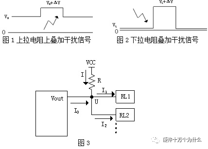
When the front output is high, Vout outputs current and U is high. There are two situations:
A. When I0 >= I1 + I2
In this case, the two loads RL1 and RL2 do not take current through R, so the R resistance value is not high, usually 4.7 KΩ. B. When I0 < I1 + I2 I0 +I= I1 + I2 U=VCC-IR U>=VHmin Calculated from the above three formulas, R<=(VCC- VHmin)/I Among them, I0, I1, I2 can be found from the datasheet, I can be obtained, VHmin can also be found. When the current Vout output is low, each pin is sinking current, then: I'= I1' + I2' +I0' U' =VCC-I' R U' <=VLmax The above three formulas can be drawn: R>=(VCC- VLmax)/I' The upper and lower limits of R are calculated from the above two equations, and a value closer to the intermediate state can be taken from it. Note that if the number of loads is variable, the calculation must be made according to the worst case scenario. The upper limit value should be calculated at the time when the load is maximum, and the lower limit value should be calculated based on the least load. Another alternative is based on power considerations. According to the actual application of the circuit, the frequency or time ratio of the output signal state is selected. If the signal Vout is at a low level for a long time, the pull-down resistor should be selected. If the signal is at a high level for a long time, a pull-up resistor should be selected. For the quiescent current is small. Sixth, current Sink current: Irrigation charge, passive input current, inflow current from the output port: Suction is the active suction current, which is the current flowing from the input port to the sink current and the sink current, which is the current flowing from the chip to the chip through the pin. The difference is that the sink current is active. The current flowing in from the chip input terminal is called the sink current. The current injected is passive, and the current flowing from the output is called sink current. Pulling current is the output current provided by the digital circuit output high level to the load. When the current is sourcing, the output low level is the external input current to the digital circuit. They are actually input and output current capabilities. The sink current is for the input (input suction); The pull-out current (outflow at the output) and the sink current (injection at the output) are relative to the output. Forging is one of the two components of forging (forging and stamping), which is a processing method that makes use of forging machinery to exert pressure on metal billets and produce plastic deformation to obtain forgings with certain mechanical properties, certain shape and size. Through forging can eliminate the defects such as loose cast state produced in the smelting process of metal, optimize the microstructure structure, at the same time because of the preservation of a complete metal streamline, the mechanical properties of the forging is generally better than the same material castings. Forgings are mostly used for the important parts with high load and severe working conditions in the relevant machinery, except for the simple plate, profile or welding parts that can be rolled. Hot Forging,Forging Mine Chain Link,Custom Made Forging,Alloy Steel Forging Mine Chain Tianhui Machine Co.,Ltd , https://www.thcastings.com