In the field of automatic control of production machinery, the application of the plc sequential control system is extensive. However, different production machines with different processes require different control system ladder diagrams. At present, many electrical designers still use the empirical design method to design the PLC sequential control system. Not only is the design efficiency low, it is easy to make mistakes, and it is difficult to find errors in the design stage. It requires multiple debugging and modification to meet the design requirements. The four simple design methods proposed in this paper can quickly design a successful PLC sequential control system.
The characteristics and design ideas of sequential control system
1. The characteristic sequence control system refers to an automatic control system that is carried out step by step according to a predetermined controlled actuator operating sequence and corresponding transition conditions. The controlled equipment is usually a production machine with the same order of motion or relatively fixed. Most of the control system's main steering signals are travel switches (including contact or non-contact travel switches, photoelectric switches, reed switch, Hall switch, etc.), and sometimes pressure relays. A signal conversion component such as a time relay is used as a step-by-step master signal for some steps.
In order to make the sequential control system work reliably, a stepwise sequential control circuit structure is usually employed. The so-called step-by-step sequence control means that the power of any step of the control system (hereinafter referred to as the step) must be powered by the previous step and the step-by-step master signal of this step has been issued as a condition. For production machinery, whether the mechanical action of any step of the controlled equipment is performed depends on whether the output signal and its controlled mechanical action have been completed in the previous step of the control system. If the action of the previous step is not completed, the action of the next step cannot be performed. The interlocking of such a control system is not uniform, and even if the main signal of the step-by-step command is malfunctioning or misoperation occurs, the operation sequence will not be disordered.
2. Design Ideas The four simple design methods proposed in this paper are to design the step ladder first. In the step ladder, the auxiliary relay is controlled by the turn-step master signal to obtain power loss. Then, according to the step ladder design output ladder, the output ladder is realized by the auxiliary. The relay control output relay is de-energized. The ladder circuit structure and corresponding instructions designed by these four design methods should be applicable to most PLC models and have versatility.
Since the programming component codes and their serial numbers of various PLC models are not the same, for the convenience of explanation, this paper stipulates that the code numbers of input relays, output relays, and auxiliary relays (also called internal relays) in all ladder diagrams are: X, Y, M. Some of the functional instructions used in the design, such as the set instruction convention is S ×, the reset instruction is R ×; the shift instruction is SR ×. The "x" in it indicates the number of the programming component and is represented by a decimal number. When designing the actual control system using these methods, the programming component code and number should be converted to the code and number corresponding to the selected PLC model.
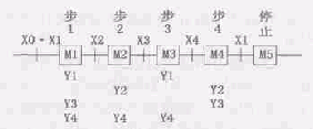
Figure 1 sequence control process
The various design methods are described below. Among them, the design of the first three methods is based on the sequence control flow shown in Figure 1. In the figure, the step-by-step master command signal X0 of step 1 is the input relay connected to the start button (for the sake of brevity, the following steps are omitted: the input relay signal is omitted, only the input signal), X1 For the home position switch signal, X2, X3, and X4 are the step-by-step master switch signals of steps 2, 3, and 4, respectively. M1 to M5 are controlled auxiliary relays for each step. Y1 ~ Y4 are the output relays controlled by each step.
1. Step-by-step power-synchronous power loss type step sequence control system design method
As shown in FIG. 2, this design method is designed according to the basic logical relationship of "AND", "OR", and "NO", and is designed as a circuit structure in series, parallel or series and parallel combination.
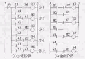
Figure 2 Step-by-step power-on synchronous power loss step-by-step ladder diagram
1. Step ladder design
As shown in Figure 2a. The M1 electrification condition of step 1 is that the controlled mechanical home position switch X1 is in a pressed state (if the controlled machine has multiple actuators, the in-situ switch of each actuator is required to be in a pressed state), and the in-situ condition is satisfied. After the condition, press the start button X0 to get power. M1 is self-locking after it is powered, and provides step condition signal (M1 normally open contact) for step 2. The stroke switch signal X2 triggered when the execution of the step 1 is completed is taken as the transition condition signal of the step 2. The input of M2 of step 2 is self-locked after satisfying its stepping condition and the turning condition, and provides a step condition signal for step 3. According to this rule, the power and self-locking of the auxiliary relay of each working step can be realized. The step condition signal and the turn condition signal of the stop step M5 are respectively: a step condition signal (the normally open contact of M4) issued by the last work step M4 and a turn signal X1 triggered when the step operation is completed. Since the power signal of the M5 causes the control system to lose power, the loop of the M5 is not self-locking, and its normally closed contact is connected in series to the leftmost end of the step 1 loop. The loops of the subsequent steps from step 2 constitute a branch circuit. Once the M5 is powered, the entire system is de-energized. If the structure of the branch circuit is not used, the circuit shown in Fig. 3 can also be used. That is, the M5 normally closed contacts are respectively connected in series on the loop of each auxiliary relay. It should be noted that, regardless of the work step or the stop step, if there are multiple main signals in a step, the multiple turn master signals should be connected in series.
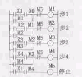
Figure 3 Step-by-step power loss synchronization elevator diagram
2. Output ladder design output ladder
As shown in Figure 2b. The design method is as follows: (1) In the control flow chart, find out which step of an output relay M starts to be powered and at which step to start power loss, thereby determining its electrical signal (M step starts in step ladder) Electrical auxiliary relay normally open contact) and power loss signal (the auxiliary relay of the auxiliary relay that causes M to start to lose power in the step ladder); (2) connect the power signal, the power loss signal and the controlled output relay coil in series . If an output relay is electrically de-energized multiple times in one duty cycle, the series signals that are de-energized each time are connected in parallel with each other. For example, the output relay Y1 of Figure 1 requires power to be energized in steps 1 and 3, and de-energized in the remaining steps. When the control loop is drawn in FIG. 2b, the first power-on signal M1 and the first power-off signal M2 shown in FIG. 1 are connected in series, and the second power-off signal M4 and the second power-off signal are connected in series, and then The two are connected in parallel, and then connected in series with the coil of Y1 to form a control loop of Y1. The rest and so on.
Second, the step-by-step power-off step-by-step control system design method
1. Step ladder design
According to the control flow shown in Figure 1, the stepping step designed by the step-by-step gradual power-off type sequential control system design method is shown in Fig. 4a. One of the differences between the circuit structure and Fig. 3 is the power loss of each step. It is controlled by the normally closed contact of the next auxiliary relay; the second is that the step 1 circuit must be connected to the auxiliary relay normally closed contact of step 2 to the last working step 4. In case the circuit is operated, the control sequence is disordered due to the erroneous operation. The remaining circuit junctions are the same as in Figure 3.
2. The output ladder design output ladder is shown in Figure 4b, and the control loop of the output relay is intuitively determined according to the control flow. For example, if the output relay Y1 is required to be energized in steps 1 and 3, the normally open contacts of the auxiliary relays M1 and M3 of steps 1 and 3 are connected in parallel, and then connected in series with the coil of Y1. The control loops of the remaining output relays are constructed in the same way.
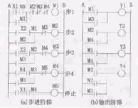
Figure 4 Step-by-step power-saving step-by-step power failure sequence control system ladder diagram
Third, the set/reset command type sequential control system design method
1. Step ladder design Figure 5a shows the step ladder of the sequential control system designed with the set/reset command. The design basis is also the control flow shown in Figure 1. The step ladder structure is characterized in that each step of the auxiliary relay has a set coil and a reset coil, and the two numbers are the same. Step 1 uses the set command S to set the auxiliary relay M1 (ie, the M1 coil is internally self-locked after powering up), establishes the step 1 program, and provides the step condition signal for step 2. When the step-by-step master signal of step 2 is issued (X2 is closed), the command S sets M2 to set the step 2 program, and the reset command R resets M1, and cancels the step 1 program. Similarly, the relay step reset/reset ladder diagram can be drawn. When the last step is completed and returned to the home position (X1 is closed), the command R resets M4 and the system's duty cycle ends.
2. Output Step Design Figure 5b shows the output ladder structure, which is identical to Figure 4b and will not be described again.
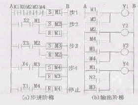
Figure 5 set/reset command type sequence control circuit
Fourth, shift instruction type sequential control system design
1. The design of the step ladder design is shown in Figure 6. Figure 7a shows the step-by-step sequence of the sequential control system designed by the shift instruction design method as shown in Figure 6. This step ladder is composed of an 8-bit shift register (the auxiliary relays M20 to M27 are defined by the shift command). As a control element. IN of the shift register is the shift data input terminal, CP is the shift pulse input terminal, and R is the reset terminal. The input signals of these three inputs are all valid for the rising edge of the pulse. For a sequential control system, the signal input to IN must be a single pulse signal, ie the shift data is "1". When starting step 1, when IN and CP simultaneously input the rising edge of the pulse of the button signal X0, the shift data "1" generated at the IN terminal is shifted into the M20 bit of the shift register. At this time, the bit has an output (ie, the output M20 Normally open contact closure signal), establish step 1 program, and provide step condition signal for step 2; M20's normally closed contact instantly disconnects IN input and CP step 1 input to complete data "1" input and Shift pulse input. From step 2, the main step signal of this step is issued (X2 is turned on), then a rising edge of the shift pulse is input, so that the data "1" originally moved into the M20 bit is moved into the M21 position, and the step 2 program is established, and Step 3 is provided for the step condition signal. After shifting, the state of the M20 bit becomes 0, that is, its corresponding step 1 is deactivated and the output is 0. By analogy, the entire step step can be gradually powered and gradually lost. When the last step is completed and returned to the home position (X1 is turned on), the reset terminal R of the shift register is turned on, the shift register is reset to zero, and the entire control system is de-energized to stop.
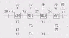
Figure 6 shift sequence control flow chart
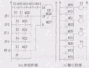
Figure 7 shift instruction type sequence control circuit
Pay attention to the following problems when designing this step ladder: (1) In an automatic duty cycle, the shift data input terminal IN of the shift register is only allowed to input a single pulse signal at startup. This means that only the shift data "1" can be entered at startup. The working principle of the step ladder is to gradually realize power-on and step-by-step power loss according to the input data "1" in the shift register to the high-displacement bit. Therefore, the input terminal IN should be connected in series with the normally closed contact of each shift output bit; (2) the shift register is very sensitive to the jitter of the shift pulse input switch. If the switch is shaken once, it is equivalent to inputting one shift pulse, and the shift data "1" is shifted by one more. It is inevitable that jitter will occur when the contact switch is triggered. In order to eliminate this effect, in the step 1 input loop of the shift pulse input terminal, the normally closed contact of the shift register 0 bit (in this example, M20) must be connected in series. Once the shift data is shifted into the M20 bit, the step 1 is disconnected. Input loop; starting from step 2, the input loop of each step is also connected in series with one of the normally open contacts. For example, the input loop of step 2 should be connected in series with a normally open contact of M20. Thus, when shifting to the M21 bit corresponding to the step 2 main command signal, the input loop of step 2 is immediately turned off. By adopting such a shift pulse input loop structure, it is ensured that the duration of the step input signal of each step is only one scan period of the PLC (generally only a few Ms), because the jitter time of the switch is much larger than one scan period of the PLC. Therefore, the influence of switching jitter can be effectively eliminated.
2. Output ladder design Figure 7b is the output ladder, the structure of which is the same as Figure 4b, except that the auxiliary relay numbers are different.
Conclusion
The common features of the above four PLC sequential control system design methods are:
(1) The auxiliary relay is controlled by the input relay (including the auxiliary relay defined by the set/reset command and the shift command), and the step ladder is configured accordingly;
(2) controlling the output relay by the auxiliary relay to form an output ladder;
(3) Both the step ladder and the output ladder are very regular loop structures. Regardless of the number of steps in the sequential control system to be designed, and regardless of the number of input and output points, as long as the regularity of the loop structure of the step ladder and the output ladder designed by various design methods is clarified, according to the design basis, the application is applied. A loop structure of the design method can quickly and successfully design a more complicated PLC sequential control system.
Horn Tweeter,Voice Coil,Neodymium Magnet Tweeter,Voice Coil Compression Drive
NINGBO BOILINGSOUND ELECTRONICS CO.,LTD , https://www.tweeterspeaker.com