With the development of modern electronic technology, modern electronic devices with various micro-processing have been widely used in various industries of national production. However, as the function of the device becomes more and more powerful, the program structure becomes more and more complex, the instruction code becomes longer and longer, and the interference of the on-site working environment, the device is out of control, the program "goes away", and the probability of each function module "dead" is also the same. Increased exponentially. A common solution to this is to place a hardware watchdog circuit in the circuit design. The purpose is to force the system to reset and return to the initialization routine after the system "walks away". As CPLD devices are widely used in the design of various instruments and instrumentation, and CPLD can simulate almost any kind of logic circuit, it is no longer necessary to place a separate watchdog device at the time of design. The hardware watchdog circuit can be integrated into the CPLD device, saving cost and reducing system design risk. The design of the watchdog circuit based on CPLD technology is specifically described below.
working principle
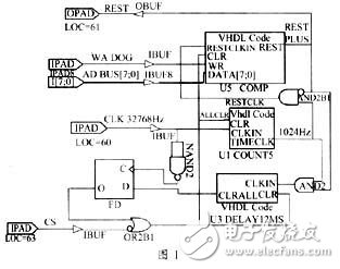
CPLD is the abbreviation of English Complex Programmable LogICDevice. The Chinese name is complex programmable logic device. Because of its high efficiency, small internal delay and predictable delay, it is widely used in counters, logic circuits, control circuits and The implementation of functions such as complex state machines, and the core of the watchdog circuit is a counting timing circuit. Therefore, the function of the watchdog circuit can be well realized by using the characteristics of the CPLD. The block diagram of the watchdog circuit is shown in Figure 1. It can be divided into three parts: frequency dividing circuit, counting timing circuit and reset circuit. Its working mode is to input a 32768Hz square wave clock into the frequency dividing circuit, and the divided square wave is input into the counting timing circuit. Counting, at the same time compared with the set counting time constant, when the CPU does not clear the CS terminal state by changing the state of the CS terminal within the specified time, once the count value is consistent with the preset value, the counting timing The circuit will generate a high level to the reset circuit, which will generate a reset signal to the REST terminal of the CPU. For example, for the MCS51 family of microcontrollers, a high level greater than 10ms will be generated to ensure a reliable reset of the CPU.
Complex programmable logic device
Circuit design
At present, XILINX's programmable devices are widely used in various products due to their good design platform, secure encryption methods, and complete product lines. Below, take the X95 series CPLD in its product line as an example to introduce the design of the watchdog circuit.
Watchdog circuit design
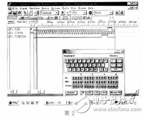
Frequency dividing circuitThe circuit is implemented by the U1 COUNT5 macrocell in Figure 1. The purpose of the macrocell is to pass a 32768kHz rectangular pulse through a 5-bit binary counter, and divide by 32 to obtain a 1024Hz square wave, that is, A square wave with a period of about 1 ms has a simulated waveform as shown in Fig. 2.

Watchdog circuit design
Among them, CLKIN is a 32762Hz square wave signal, CLR is the frequency divider clearing end, and TIMECLK is the output of the 32 frequency divider. As can be seen from the figure, when CLR is low, the divider operates, and when CLR is high, the divider is cleared.
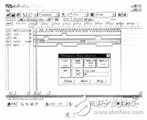
This circuit is the core circuit of the watchdog. Its function is implemented by the U5 COMP macrocell in Figure 1. The macrocell consists of an 8-bit binary counter, an 8-bit register, and an 8-bit comparator. The initial value of the 8-bit register is 0FFH, which can also be set by the 8-bit data port of the AD BUS and the WR DOG chip select port. When the 1024Hz square wave enters the 8-bit counter for counting, the comparator will also compare the counter's count value with the register. Once the two are equal, the comparator will generate a REST high level, prohibiting the counting pulse input and simultaneously opening the reset circuit. Counter. The simulation waveform is shown in Figure 3.
Counting timing circuit
Where RESTCLKIN is the 1024 Hz reference clock input. The CLR is the 8-bit counter clearing terminal. WR is the chip select latch of the 8-bit register (rising edge latch). DATA7 is an 8-bit data bus for presetting 8-bit registers. REST is the reset output and provides a high level to ensure a system reset.
Reset delay circuit
The function of this circuit is completed by the U3 DELAY12MS macro unit. The purpose is to keep the REST signal stable at a high level of 10ms or more after the REST signal is generated to ensure a reliable reset of the system and generate a high after the delay. The level clears all macrocell counters. The simulation waveform is shown in Figure 4.
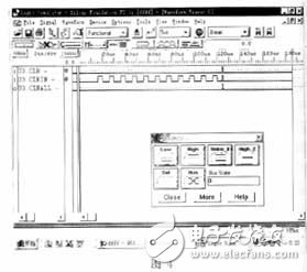
Among them, CLKIN is a 1024 Hz reference clock pulse, and is allowed to input the U3_DELAY12MS macrocell when the U5_COMP macrocell REST output is high. When the counter counts as 12, the U3_DELAY12MS macrocell CLRALL generates a high level, which is latched into the D-type register by a 32768Hz pulse. The output of the D-type register will clear all counters and compare the U5_COMP macrocells. The output of the device is "0", thus ending the reset.
At present, I have adopted this design in the designed products. It has been proved that integrating the watchdog circuit through the CPLD device can effectively ensure the normal operation of the system and reduce the separate placement of the watchdog device. Design risk and additional costs.
Solderless Breadboard,400 Point Breadboard,3M Solderless Breadboard,Solderless Breadboard Kit
Cixi Zhongyi Electronics Factory , https://www.zybreadboard.com