Researchers Bai Yi, Shi Yanyan, Zhang Qiaojie, and Bai Lianping of the School of Automation, Beijing University of Information Science and Technology, wrote in the first issue of "Electrical Technology" in 2018 that in the generation of ocean energy, tidal power generation has broad prospects for development. A set of tidal power generation experimental devices for preliminary research in the laboratory laid the foundation for offshore trials of tidal power generation.
In the power flow simulation device control system, the frequency conversion speed regulation of the three-phase asynchronous motor by using the frequency converter is the key technology in the power flow simulation. To this end, the LabVIEW operation interface and block diagram are designed on the host computer. The VISA technology is used for data transmission. The RS485 communication is used to control the continuous operation of the inverter, so that the three-phase asynchronous motor is driven to drive the two-way impeller pump to push the water to flow. Simulation study.
The rapid development of the economy has made traditional fossil energy sources far from meeting the needs of modern economic and social development because of the declining storage capacity, non-renewability and environmental pollution. Ocean can provide a lot of valuable energy for human beings in the form of tides, waves, temperature differences, salt differences, etc. The trend can be favored for its large storage capacity, high energy density and predictability.
In the study of tidal power generation, the cost of offshore testing is high, and the test of generators is difficult. It is necessary to design a complete set of laboratory tidal power generation simulation devices as the preliminary research equipment for tidal current generators. Therefore, this paper studies the tidal current power generation simulation device and its control method, and realizes the preliminary research on tidal power generation in the laboratory.
1 tidal power generation simulation device system
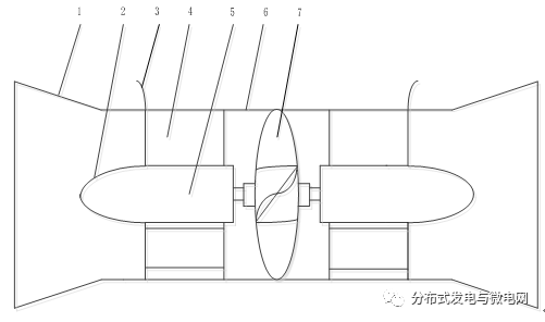
The schematic diagram of power generation equipment for tidal power generation at sea is shown in Figure 1. 1-Confluence hood, 2-flow hood, 3-generator lead, 4-generator support, 5- permanent magnet generator, 6-round Draft tube, 7-"S" bidirectional impeller. The manifold converges the current in the diversion tube, increases the flow rate of the water, and drives the concentrated rotor to rotate the generator rotor to generate electricity. In the laboratory to simulate offshore power generation, the draft tube and generator part of the device is essential, so the laboratory tidal power model
Figure 1 Schematic diagram of offshore power generation equipment
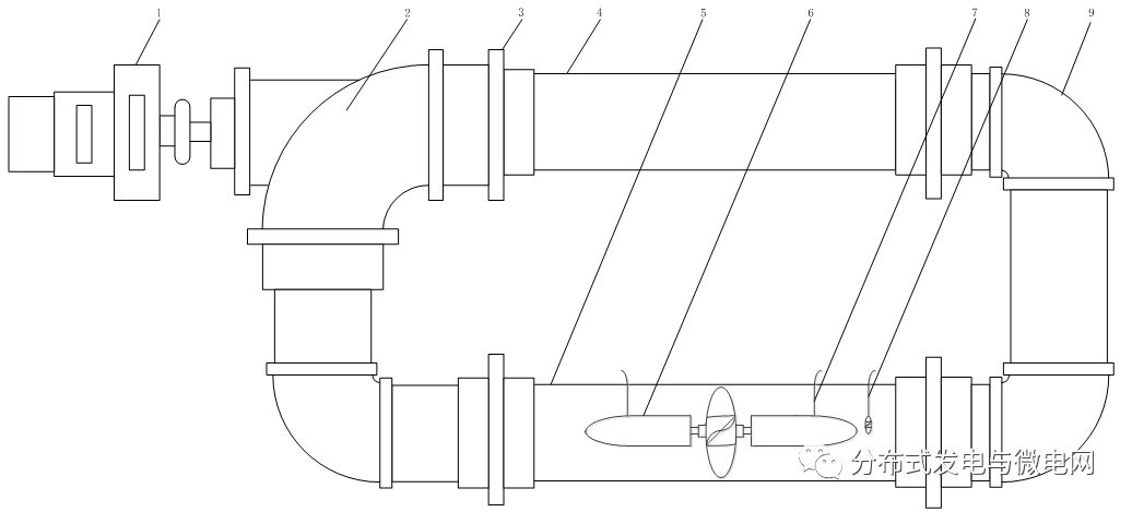
The proposed device is designed as a water flow closed loop with controllable flow rate. The schematic diagram is shown in Figure 2. Among them, 1-motor, 2-way impeller pump, 3-connecting flange, 4-conductor, 5-plexe glass guide, 6-impeller direct drive generator, 7-auxiliary seal, 8-flow sensor . 9-bend pipe.
The upper computer converts the corresponding water flow speed function according to the energy parameter of the tidal current to control the output frequency of the frequency converter. The inverter drives the motor, and the motor drives the two-way impeller pump to generate the desired water flow, thereby realizing the flow of water corresponding to different tidal currents.
2 Research on control method of power flow simulation device
In the tidal current power generation simulation device, the primary task is to control the three-phase asynchronous motor to run continuously in reverse rotation through the frequency converter. There are three ways to control the inverter output frequency change: (1) by manual operation of the inverter button control; (2) by externally input analog signal control; (3) by serial communication command control.
For the power flow simulation control system, the manual control of the first method is more complicated, and the degree of automation is also lower; the adjustment accuracy of the second method is not high enough; the third method is used to set the frequency through serial communication, in addition to the high degree of automation. In addition to accurately setting the frequency, the continuous control of the inverter can be programmed to simulate the power flow [1].
The development of serial communication programs is usually written in languages ​​such as VB, VC, Delphi, etc. However, when programming with VB and VC, it has to face complicated API functions, which makes the writing of the program very complicated, because Delphi does not provide Serial communication software, so Delphi serial communication programming has become less likely [2].
Therefore, through the VISA serial communication technology of LabVIEW, the RS485 interface is used to realize the frequency conversion speed regulation of the three-phase asynchronous motor according to the Modbus communication protocol, and the upper machine controls the power flow simulation device.
Figure 2 Schematic diagram of the tidal current power generation simulation device
2.1 Introduction to LabVIEW and Serial Communication
With the rapid development of science and technology, information sampling, data processing and automatic testing in the field of virtual instrument technology have been widely used, which has promoted changes in the application methods of detection systems and process control. The LabVIEW released by National Instruments (NI) in the United States greatly shortens the gap between software usability and powerful functions. It uses high-performance modular hardware to complete signal acquisition and processing, and uses efficient software to perform signal calculation and analysis.
The main features of the LabVIEW application are as follows:
(1) A good user interface can be designed, and the front panel is based on instrument-related terms and icons, such as switches, knobs, buttons, input and output controls, and the like.
(2) Programming adopts graphical programming, which is simple and intuitive. The written program is displayed in the form of a block diagram in the back panel. It is as easy to understand as the data flow chart. It is undeniably known as the real engineer language.
(3) The debugging program method is simple and diverse. In addition to the traditional single-step operation and setting breakpoints where necessary, the probe can also be set in the block diagram according to requirements, and the real-time value can be displayed online while the program is running; It can also be "highlighted" when debugging the program. It is convenient to observe the running details of the program and judge the correctness of the program through the flow of the data stream.
(4) Communication bus standard with multiple instruments, support ActiveX, TCP/IP, DLL (Dynamic Link Library) and other functions. It can be jointly developed by other system platforms, with strong compatibility, and convenient program porting to make LabVIEW program application more powerful.
VISA (Virtual Instruments Software Architecture) is a new-generation instrument I/O standard. It exchanges data between the host computer and serial port, USB, GPIB, Ethernet, PXI or VXI by the type of instrument. ]. VISA uses the same API for different operating systems, buses, and programming environments.
The serial port is a physical layer interface standard. The serial port is divided into RS232, RS422, RS485, etc. according to the electrical standard of the specified interface. The main difference is that the level of the receiving level signal is different [4]. The two-wire system adopted by the RS485 interface realizes multi-point two-way communication, and has better performance than RS232 in many aspects such as communication speed, transmission distance, and multi-machine connection.
The signal level of the RS485 interface is lower than that of the RS232, and the chip of the interface circuit is not easily damaged. Its maximum transmission data rate is 10 Mbit/s. In order to reduce the noise immunity, the RS485 interface that constitutes the half-duplex network not only uses twisted-pair shielded cable transmission, but also uses a combination of balanced driver and differential receiver.
The RS485 interface has multi-station capability compared to the single-station RS232 interface on the bus, and can be connected to 128 transceivers. Terminal X1:28~32 of the inverter ACS550 control board is the RS485 communication interface of the inverter.
The serial asynchronous communication protocol Modbus protocol developed by Modicon in 1979 is the first bus protocol for industrial field. Half-duplex data transmission allows one master to control multiple slaves. Due to its ease of use, the protocol supports not only RS232/RS422/RS485 but also Ethernet devices, which is very versatile in industry standards. The Modbus protocol is often used as an integrated communication between the master controller and the slave device to facilitate the formation of an industrial network.
The Modbus communication protocol has the following advantages:
(1) It has a common industry standard and can be used openly using the Modbus protocol.
(2) Support a variety of electrical interfaces, support more manufacturers, support a variety of transmission media.
(3) The frame format is simple, it is easy for the manufacturer to develop, and the user is also very convenient to use. The Modbus network defines two transmission modes of ASCII and RTU. In the same Modbus system, the two modes are not allowed to be mixed and only one of them is allowed. The ACS550 drive only supports RTU mode. The RTU mode requires less data bits when expressing the same data information than the ACSII mode, resulting in greater data traffic [5].
The Modbus RTU mode data frame has no start and stop bits, and each frame has at least 3.5 character intervals. The data frame is composed of a hexadecimal address code, a function code, a data code, and a check code. The Modbus data frame format is shown in Table 1.
Table 1 Data frame format

The Modbus function codes supported by the inverter ACS550 are shown in Table 2.
Table 2 Modbus function table
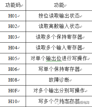
Table 3 shows the format of the data frame message for communication between the host computer and the inverter.
Table 3 Message format

2.2 Inverter parameter setting
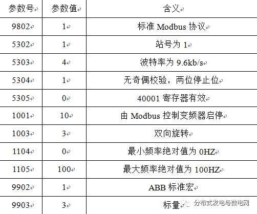
The station number, baud rate, parity bit, and stop bit that the inverter needs to set must be the same as the communication parameter settings of LabVIEW before data can be transmitted. The parameter settings for the ACS550 drive are shown in Figure 4 [7].
Table 4 Inverter parameter settings
2.3 Communication system programming
The basic steps for using the VISA technology for serial communication in the LabVIEW block diagram are as follows:
First: Serial port initialization, use VISA Configure Serial Port.vi to set basic parameters of serial communication.
Second: read and write the serial port, through the VISA Read.vi and VISA Write.vi for serial port read and write operations on the transmission data.
Third: close the serial port, use VISA Close.vi to close the serial port, no data transmission.
According to the communication parameters of the inverter and the Modbus communication protocol, the RS485 communication control program of the inverter is shown in Figure 4. The specific steps of the LabVIEW block diagram design can be divided into the following steps according to the flow of data [6].
(1) VISA configuration serial port, including VISA resource name, namely inverter port number selection, baud rate, data bit, parity and stop bit, its parameter setting is consistent with the inverter parameter setting of Table 4.
(2) Initialize the inverter and write the hexadecimal number 0476 to the 40000 register of Modbus with a delay of 200 milliseconds.
(3) Start the motor, that is, write the hexadecimal number 047F into the 40000 register of Modbus.
(4) Convert the decimal frequency (range -100~100H) input from the front panel to hexadecimal.
(5) Calculate the CRC check code according to the lower 16-bit calculation rule of Modbus RTU mode.
(6) Send the merged data frame to VISA Write.vi to write to the serial port.
(7) Turn off the serial port and no longer transfer data to the inverter.
3 Experimental results
The tidal current power generation simulation experiment device designed according to Fig. 2 is shown in Fig. 3. The program running interface of the power flow simulation device is simple and convenient as shown in Figure 5. Just select the port number of the corresponding inverter on the computer, then click the start button, the inverter initialization is completed, then input the frequency, click the change frequency button, the motor Rotate at a given frequency. If you want to change other frequencies, you can input the frequency directly in the frequency box without clicking the button.
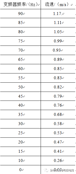
If continuous control is required, simply change the frequency value input to the frequency array input. First stop the inverter by clicking the Stop 1 button and then clicking the Stop 2 button. The simulation of the tidal current generation is performed on the simulation device, and the obtained flow velocity simulation data is as shown in Table 5, which is consistent with the actual flow velocity of the offshore tidal current power generation device of FIG.
Figure 3: Power flow simulation simulator

Figure 4 communication control program diagram
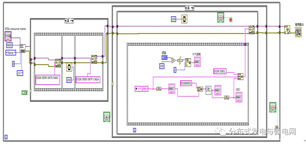
Figure 5 system operation interface
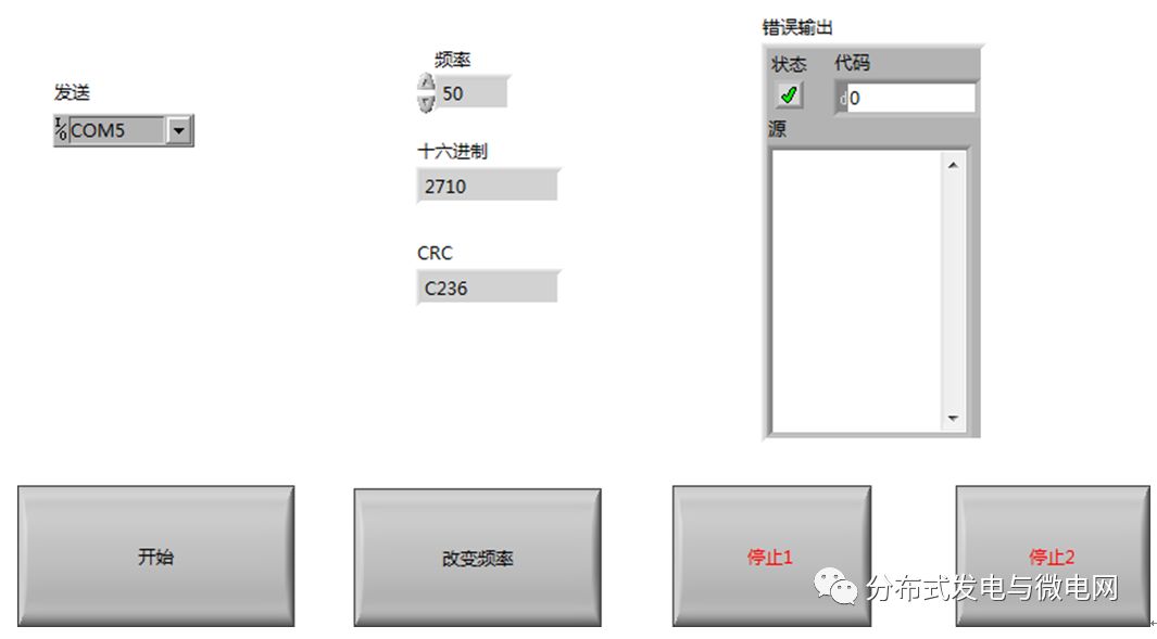
Table 5 Flow rate measurement data at different inverter frequencies
4 Conclusion
This paper designs a set of laboratory power generation simulation devices, which has the advantages of compact structure, high efficiency and low cost. In its control system, it communicates with RS485 interface of LabVIEW and ACS550 inverter, realizing the real-time control of the inverter by the host computer, which drives the motor to drive the water pump to push the water. After the test and the actual flow rate coincides in a certain period of time, A simulation of power flow generation in the laboratory was achieved.
The device provides the necessary experimental conditions for the study of tidal power generation, impeller optimization design, impeller energy conversion efficiency, tidal current generator efficiency, and generator energy processing. It laid the foundation for offshore trials of tidal power generation.
Poly Solar Panel,Solar Panel Module,Polycrystalline Solar Panel,Poly Crystal Solar Panels
Wuxi Sunket New Energy Technology Co.,Ltd , https://www.sunketsolar.com