Example 1: The line scan flyback switch transformer used in the TV set, referred to as the high voltage package, also works as a flyback switch transformer. The inductance of the primary coil is 6 millihenries, and the working voltage is generally 120V. The time (pulse width) is 52 and the reverse scan time is 12. Check if its volt-second capacity is well designed or if it is working at its best.
To this end, we can calculate the maximum current Im flowing through the primary coil of the high voltage package according to the formula (2-150), and then find the value of the limiting current Imax, that is, the value of the superimposed current is selected during the test.
Substituting known parameters into (2-150):

According to the above analysis, and Figure 2-55 and Figure 2-56, during normal operation, the maximum current Im flowing through the primary coil of the high voltage package should not exceed 70% of the limit current value Imax, thereby allowing the flow through the high voltage package. The limiting current Imax of the primary coil is 1.49 A.
The limit current Imax value calculated above is the value used to test the superimposed current of the primary coil of the high voltage package. According to Figure 2-54, set the current of the current source to 1.49 A, that is, set the superposition current of the primary coil of the test high voltage package to 1.49 A, and then test the inductance of the primary coil of the high voltage package; if the test result is Lx The value is equal to or greater than 90% of the initial inductance L0, indicating that the volt-second capacity design of the high voltage package primary coil is qualified, that is, the magnetic induction strength of the high voltage package core is basically working within the optimal state range; if the test result Lx Less than 90% of the initial inductance L0 indicates that the volt-second capacity margin of the primary coil of the high voltage package is too small to be unqualified, that is, the magnetic induction of the high voltage core is working within the range close to the saturation region, and the hysteresis loss is The eddy current loss is relatively large, and the switching transformer is prone to magnetic saturation.
In addition to testing the volt-second capacity of the high-voltage package or switching transformer, the leakage inductance of the high-voltage package or the primary winding of the switching transformer should also be detected. The value of the normal leakage inductance is generally less than 2% of the inductance of the primary coil. If it is too large, the length of the air gap left by the transformer core is too large, or the structure of the primary and secondary coils of the switching transformer or the winding method is unreasonable.
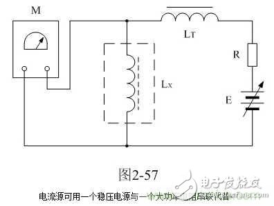
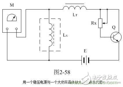
Here, by the way, you should pay attention to the test when using the test in Figure 2-54. In Figure 2-54, the size of the isolation inductor LT is more than three times the value of the test inductor Lx. When measuring the initial inductance value L0 of the high voltage package primary coil, it is better to also access the circuit. Here, the isolation inductor LT can select an inductor with a silicon steel core of 20 millihenger or more, and the core of the inductor should have a certain air gap; the current source can be replaced by a constant voltage power supply and a high power resistor, as shown in Fig. 2. -57; or use a regulated power supply in series with a high power crystal amplifier instead, as shown in Figure 2-58.

In Figure 2-57, E is a regulated power supply, R is a high-power resistor, and the resistance range is 1 to 10 ohms. The resistance is too large and the power loss is large. Adjusting the voltage output of the regulated power supply can Adjust the magnitude of the superimposed current.

In Figure 2-58, E is a regulated power supply, Rx is an adjustable resistor, Q is a transistor high-power amplifier (must with a heat sink); adjust the voltage output of the regulated power supply, or change the resistance of the variable resistor, The magnitude of the superimposed current can be changed, but the voltage drop between the collector and the emitter of the transistor high power amplifier should not be greater than 10V. Otherwise, the loss of the transistor high power amplifier will be large. Generally, the regulated power supply has a current output indication, so there is no need to install an ammeter in the test circuit.
It is pointed out here that when testing the initial inductance L0 of the high voltage package or the primary winding of the switching transformer, the core of the high voltage package must be demagnetized, otherwise the test result will be inaccurate. In general, the inductance of the primary coil of a magnetically-switched switching transformer is slightly greater than the inductance of a primary winding without a magnetic switching transformer. For the method of demagnetization of the high voltage package, please refer to the following "2-1-22-4. The content of the section on the degaussing method of the switching transformer.
In addition, the maximum current Imax used to test the superimposed current of the high voltage package is generally several times that of the primary coil current (average value or effective value) when the high voltage package is in normal operation. For example, in the high voltage package tested in the above example, the average current IA is only about 0.42 A during normal operation, but the value of the superimposed current Imax is 1.49 A; thus, the value of the superimposed current Imax is normal. The average current is 3.5 times. Generally, the current density of the primary coil enameled wire of the high voltage package is about 3 A/mm 2 , so the maximum current density of the current flowing through the enameled wire of the primary coil of the high voltage package is about 10.5 A/mm 2 .
Generally, the maximum current density of the enameled wire is about 13A/mm2 (DC) under the condition of 40 degree temperature rise. Therefore, it is also known whether the selection of the high voltage package coil enameled wire is reasonable by measuring the temperature rise of the high voltage package coil.
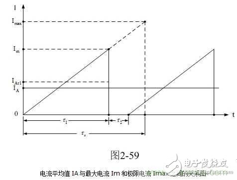
Here, by the way, the current average IA is found, and its relationship with the maximum current Im and the limit current Imax. Figure 2-59 is a graph showing the relationship between the current average IA and the maximum current Im and the limit current Imax.

In Figure 2-59, IA is the average current flowing through the primary coil of the high voltage package. IAÏ„1 is the average current flowing through the primary coil of the high voltage package during the forward scan; Im is the maximum flow through the primary coil of the high voltage package during the forward scan. Current; Imax is the limit value of the primary coil current flowing through the high voltage package during the forward scan; Ï„ is the TV forward scan time (52us), Ï„2 is the TV reverse scan time (12us), and Ï„x is the limit of the forward scan time. value.
180W Desktop Power Adapter,19V180W Desktop Charger,4V7.5A 180W Power Adapter,24V7.5A180W Switching Power Supply
Guangdong Mingxin Power Technologies Co.,Ltd. , https://www.mxpowersupply.com